English
 Español
 عربى
عربى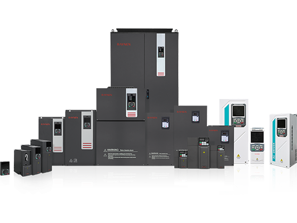
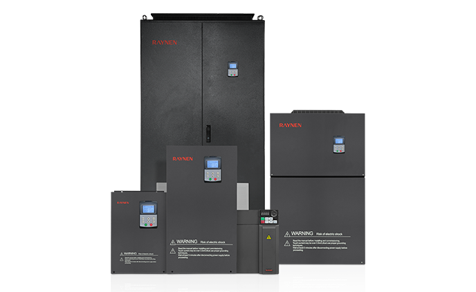


1.Introduction to AC Drives (Variable Frequency Drives) In the realm of modern industrial control an......
READ MOREThe Physics of Control: Delving into AC Servo Drive Architecture
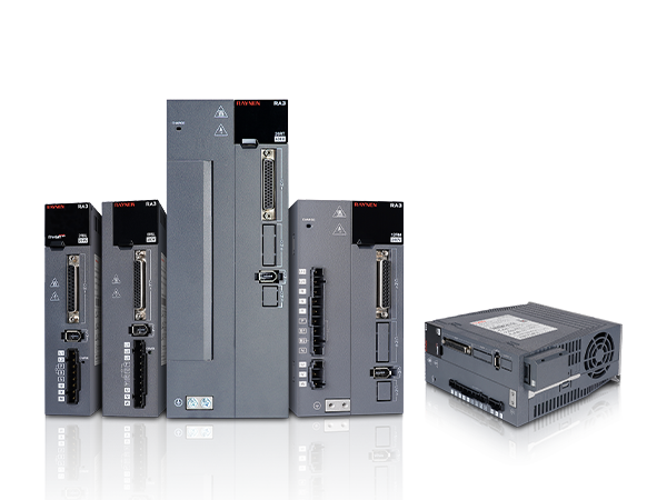
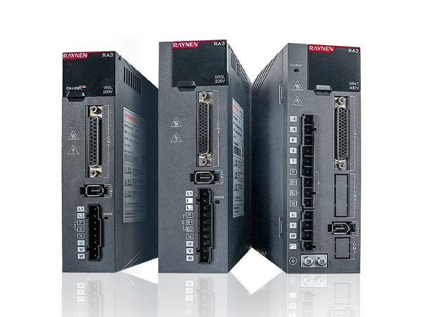
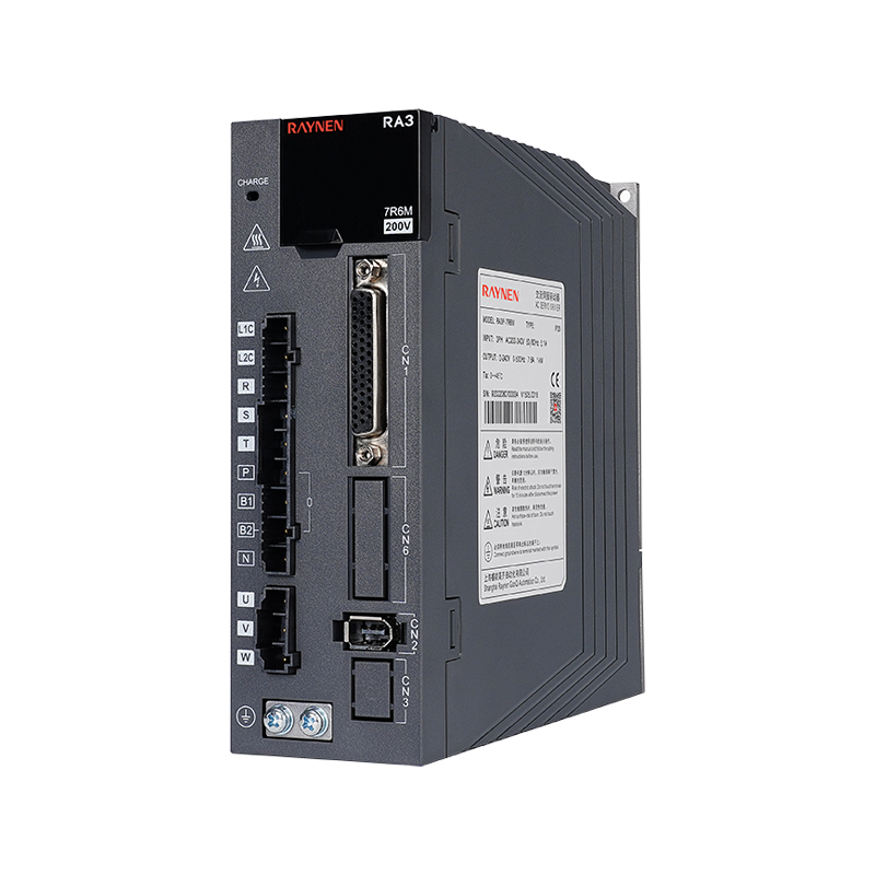
The AC Servo Drive is a sophisticated piece of power electronics that represents a triumph of control theory applied to electrical engineering. To understand its high-performance capabilities, it's essential to look beyond its functional role and examine its internal architecture—the components and processes that enable precise motion.
Internal Architecture: The Three Main Subsystems
An AC Servo Drive is generally composed of three primary functional stages that convert incoming AC power into precisely controlled AC power for the motor, based on feedback signals:
-
Power Conversion Stage (The Rectifier):
-
The incoming single-phase or three-phase AC power is first converted into a high-voltage DC (Direct Current) voltage, which is typically smoothed using a DC-link capacitor bank.
-
The energy stored in this DC bus is then available for the next stage.
-
Note:The drive may also incorporate a braking resistor or regenerative circuitry to dissipate or reuse excess energy generated during motor deceleration.
-
-
Power Inversion Stage (The Inverter):
-
This is the core power switching section, typically comprising an array of Insulated-Gate Bipolar Transistors (IGBTs).
-
The control board uses Pulse Width Modulation (PWM) techniques to rapidly switch the IGBTs, converting the DC voltage back into a three-phase AC waveform.
-
Crucially, the drive controls the frequency, magnitude, and phase of this output AC waveform with extremely high resolution to precisely manage the motor's speed and torque.
-
-
Control and Processing Stage (The Brain):
-
This includes the microprocessor or Digital Signal Processor (DSP) that executes the control loops.
-
It processes the incoming position/velocity commands and uses real-time feedback from the motor's encoder or resolver.
-
It then runs the PID control loops and Field-Oriented Control (FOC) algorithms to calculate the exact PWM firing signals required for the inverter stage to eliminate any error between the command and the actual motor position.
-
The Critical Role of Field-Oriented Control (FOC)
The superior performance of the AC Servo Drive compared to a standard VFD comes down to its use of Field-Oriented Control (FOC), sometimes called Vector Control.
-
The Problem: Controlling an AC motor is complex because the torque and flux are coupled (interdependent).
-
The FOC Solution: The DSP in the drive mathematically transforms the motor's three-phase AC currents () from the physical stator reference frame into a rotating two-axis DC reference frame ().
-
The d-axis current () controls the magnetic flux (or field).
-
The q-axis current () controls the torque.
-
-
The Advantage: By decoupling flux and torque, the drive can precisely and rapidly command the torque, giving the motor a high dynamic response similar to that of a high-performance DC motor. This is essential for the quick acceleration and precise positioning that define a servo system.
Power Rating Considerations
When selecting an AC Servo Drive, its power rating is critical and must be matched to the motor and application demands. This rating defines the drive's ability to handle the required:
-
Continuous Current: The current the drive can safely supply during continuous operation (steady state).
-
Peak Current: The maximum current the drive can supply for a short duration (e.g., during rapid acceleration), which determines the system's dynamic response.
The sophisticated architecture of the AC Servo Drive is what enables it to reliably deliver high peak currents for dynamic movement while maintaining extremely precise control over position, speed, and torque, making it indispensable in advanced automation.
Previous Post
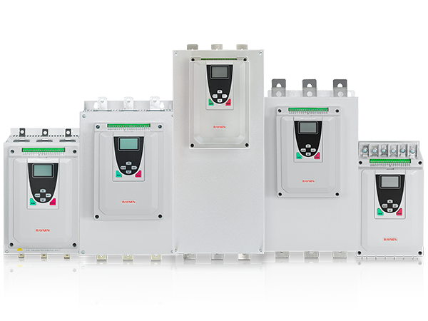
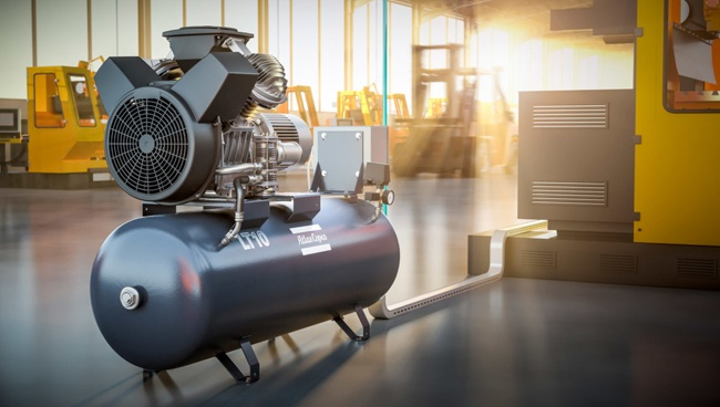
Enhancing Motor Control: The Role of the Low-Voltage Soft Starter
Next Post
What motor characteristics must be considered when selecting an AC drive?
Copyright 2024 Fujian Raynen Technology Co.,Ltd. All Rights Reserved.
Privacy Policy  Motor Control Manufacturers