English
 Español
 عربى
عربى
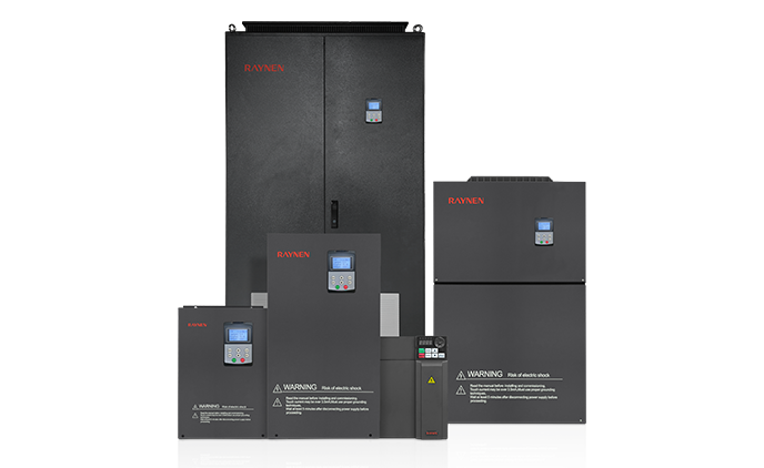


1.Introduction to AC Drives (Variable Frequency Drives) In the realm of modern industrial control an......
READ MOREVariable Frequency Drives (VFDs): A Comprehensive Guide
Content
- 1 Introduction to Variable Frequency Drives (VFDs)
- 2 2. How a VFD Works
- 3 3. Benefits of Using VFDs
- 4 4. VFD Applications
- 5 5. Types of VFDs
- 6 6. VFD Installation and Configuration
- 7 7. VFD Maintenance and Troubleshooting
- 8 7.3 Harmonics Mitigation (Continued)
- 9 8. Advanced VFD Features
- 10 9. Selecting the Right VFD
- 11 10. Top VFD Manufacturers
- 12 11. Future Trends in VFD Technology
- 13 Conclusion
Introduction to Variable Frequency Drives (VFDs)
In today's industrial landscape, optimizing energy consumption, enhancing operational control, and extending equipment lifespan are paramount goals for businesses across various sectors. At the heart of achieving these objectives, particularly concerning motor-driven systems, lies a sophisticated electronic device known as the Variable Frequency Drive (VFD).
1.1 What is a Variable Frequency Drive (VFD)?
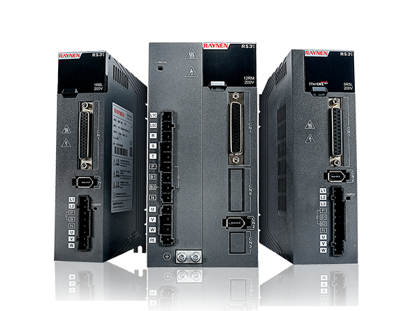
A Variable Frequency Drive (VFD), also commonly referred to as an adjustable frequency drive (AFD), adjustable speed drive (ASD), or inverter, is an electronic device designed to control the speed and torque of an AC motor by varying the motor's input frequency and voltage. Unlike traditional motor starters that simply switch a motor on or off at full speed, a VFD provides precise and continuous control over the motor's rotational speed, allowing it to operate only as fast as necessary for a given application. This capability stems from the fundamental principle that the speed of an AC induction motor is directly proportional to the frequency of the applied voltage.
1.2 Why are VFDs Important?
The importance of VFDs in modern industrial and commercial applications cannot be overstated. Their significance stems from several key advantages they offer:
- Energy Efficiency: This is perhaps the most compelling reason for VFD adoption. Many industrial processes, such as pumps and fans, often operate below their maximum capacity. Without a VFD, these motors would run at full speed, consuming excessive energy. By allowing the motor speed to be precisely matched to the load requirements, VFDs can significantly reduce energy consumption, leading to substantial cost savings and a smaller carbon footprint.
- Process Optimization: VFDs enable fine-tuning of processes that require varying speeds, such as mixing, conveying, or pumping. This leads to improved product quality, reduced waste, and enhanced overall operational efficiency.
- Reduced Mechanical Stress and Extended Equipment Life: Starting an AC motor directly across the line can create high inrush currents and mechanical shock, leading to wear and tear on the motor and connected machinery. VFDs provide a "soft start" and "soft stop" feature, gradually ramping up and down the motor speed. This reduces mechanical stress on gears, belts, bearings, and the motor itself, thereby extending the lifespan of the entire system.
- Lower Maintenance Costs: With reduced mechanical stress and more controlled operation, the frequency of maintenance and repairs for motors and associated equipment can be significantly lowered.
1.3 Basic Components of a VFD
While VFDs come in various configurations and complexities, all share a fundamental architecture comprising three primary stages:
- Rectifier: This is the input stage of the VFD. It converts the incoming alternating current (AC) power from the main supply into direct current (DC) power. Typically, this stage uses a bridge rectifier composed of diodes.
- DC Bus (DC Link): This intermediate stage stores the DC power produced by the rectifier. It usually consists of capacitors that smooth out the pulsating DC voltage from the rectifier, providing a stable DC voltage to the inverter section. This DC bus acts as an energy reservoir, helping to maintain a consistent voltage.
- Inverter: This is the output stage of the VFD. It takes the DC power from the DC bus and converts it back into variable frequency and variable voltage AC power, which is then supplied to the motor. The inverter stage typically uses insulated gate bipolar transistors (IGBTs) or other power semiconductor devices that are rapidly switched on and off to create a synthesized AC waveform.
These three core components work in concert to achieve the precise control over motor speed and torque that defines the functionality of a Variable Frequency Drive.
2. How a VFD Works
Understanding the "black box" of a VFD reveals an elegant interplay of power electronics that transforms fixed-frequency AC power into precisely controlled variable-frequency AC power. The operation can be broken down into three main stages, culminating in the sophisticated technique of Pulse Width Modulation (PWM).
2.1 Rectifier Stage: AC to DC Conversion
The journey of power through a VFD begins at the rectifier stage. The industrial or commercial power grid typically supplies alternating current (AC) at a fixed voltage and frequency (e.g., 230V/400V, 50Hz/60Hz). The primary function of the rectifier is to convert this incoming AC power into direct current (DC) power.
Most common VFDs employ a diode bridge rectifier. Diodes are semiconductor devices that allow current to flow in only one direction. By arranging six diodes in a bridge configuration, the AC input waveform is effectively "rectified" into a pulsating DC voltage. For three-phase AC input, a full-wave bridge rectifier is used, converting both the positive and negative halves of each AC cycle into a positive DC voltage. The output of the rectifier is a series of DC voltage pulses, which, while direct current, are not yet smooth.
2.2 DC Bus: Filtering and Energy Storage
Following the rectifier stage, the pulsating DC voltage flows into the DC bus (often called the DC link). This stage serves two critical purposes:
- Filtering and Smoothing: The primary components of the DC bus are large capacitors. These capacitors act as filters, absorbing the ripples and fluctuations from the rectified DC voltage. They charge during the peaks of the voltage pulses and discharge during the valleys, effectively smoothing the pulsating DC into a much more stable, near-constant DC voltage. This steady DC voltage is essential for the clean and efficient operation of the subsequent inverter stage.
- Energy Storage: The capacitors in the DC bus also serve as an energy reservoir. They can temporarily store energy, which is particularly useful during dynamic load changes on the motor or momentary sags in the input AC voltage. This stored energy ensures a continuous and stable power supply to the inverter, contributing to the VFD's robust performance.
In some larger or more advanced VFDs, the DC bus might also incorporate inductors to further enhance filtering and reduce harmonic distortion.
2.3 Inverter Stage: DC to AC Conversion
The heart of the VFD's motor control capability lies in the inverter stage. Here, the stable DC voltage from the DC bus is converted back into variable-frequency and variable-voltage AC power, which is then fed to the motor.
The inverter typically consists of a set of high-speed power semiconductor switches, most commonly Insulated Gate Bipolar Transistors (IGBTs). These IGBTs are arranged in a specific configuration (e.g., a three-phase bridge) and are rapidly switched on and off in a controlled sequence. By precisely controlling the timing and duration of these switching actions, the VFD synthesizes an AC waveform.
Unlike a true sinusoidal AC waveform, the output of the inverter is a series of modulated DC pulses. However, due to the inductive nature of the motor windings, the motor "sees" an effectively sinusoidal current, which is what drives its rotation. The frequency and voltage of this synthesized AC output are directly controlled by the switching pattern of the IGBTs.
2.4 Pulse Width Modulation (PWM)
The sophisticated technique used by the inverter to generate the variable-frequency and variable-voltage AC output is called Pulse Width Modulation (PWM). PWM is the key to how a VFD precisely controls motor speed and torque.
Here's how PWM works in a VFD:
- Fixed DC Input, Variable AC Output: The inverter takes the fixed DC voltage from the DC bus. To create a variable AC voltage output, the inverter rapidly switches the IGBTs on and off.
- Varying Pulse Width: Instead of varying the amplitude of the output voltage (as in a traditional AC supply), PWM varies the width (duration) of the DC voltage pulses that are sent to the motor.
- To increase the effective output voltage, the IGBTs are kept "on" for a longer duration within each switching cycle, resulting in wider pulses.
- To decrease the effective output voltage, the IGBTs are kept "on" for a shorter duration, resulting in narrower pulses.
- Varying Pulse Frequency: Simultaneously, the VFD varies the frequency at which these pulses are generated and the sequence in which the phases are switched.
- To increase the output frequency (and thus motor speed), the pulses are generated more rapidly.
- To decrease the output frequency, the pulses are generated less frequently.
- Voltage-to-Frequency Ratio (V/f Control): For most standard AC induction motors, maintaining a constant ratio of voltage to frequency () is crucial for optimal motor operation and to prevent magnetic saturation. As the VFD increases the output frequency to increase motor speed, it also proportionally increases the output voltage using PWM to maintain this desired ratio. This ensures that the motor's magnetic flux remains constant, allowing it to produce consistent torque across its operating speed range.
By precisely controlling the width and frequency of these DC pulses, the VFD can create an almost infinitely variable AC power supply, allowing for unparalleled control over the motor's speed, torque, and direction. This sophisticated control is what unlocks the numerous benefits of VFD technology.
3. Benefits of Using VFDs
The widespread adoption of Variable Frequency Drives across diverse industries is not merely a trend but a testament to the significant operational and economic advantages they provide. Beyond their technical sophistication, VFDs offer tangible benefits that contribute to energy savings, enhanced control, and prolonged equipment life.
3.1 Energy Efficiency and Cost Savings
This is arguably the most compelling reason for implementing VFDs. Many industrial applications, particularly those involving centrifugal loads like pumps, fans, and blowers, exhibit a quadratic or cubic relationship between motor speed and power consumption. This means a small reduction in speed can lead to a substantial reduction in energy usage.
- Quadratic/Cubic Relationship: For centrifugal loads, the power consumed by the motor is proportional to the cube of the speed (). This means if you reduce the motor speed by just 20%, the power consumption can decrease by nearly 50% ().
- Matching Load to Demand: Instead of running a motor at full speed and throttling its output (e.g., using a valve or damper), a VFD allows the motor speed to be precisely matched to the actual process demand. This eliminates wasted energy inherent in traditional control methods, leading to significant reductions in electricity bills.
- Reduced Peak Demand: VFDs can also help reduce peak demand charges by smoothing out power consumption, further contributing to cost savings.
3.2 Precise Motor Speed Control
VFDs offer unparalleled precision in controlling the speed of an AC motor. Unlike mechanical methods or fixed-speed operation, a VFD allows for continuous and infinitely variable speed adjustment across a wide range.
- Fine-Tuning Processes: This precision enables fine-tuning of industrial processes that require specific or varying flow rates, pressures, or material handling speeds. For example, in a pumping application, the VFD can adjust the pump speed to maintain a constant level in a tank, regardless of inflow or outflow variations.
- Optimized Performance: By precisely matching the motor speed to the load, VFDs ensure that the equipment operates at its optimal efficiency point, leading to better process outcomes and reduced wear.
3.3 Extended Motor Life
The way a VFD starts and stops a motor, along with its ability to run at optimal speeds, significantly contributes to extending the motor's lifespan.
- Soft Starts and Stops: Traditional direct-on-line (DOL) starting of AC motors results in high inrush currents (typically 6-8 times the full load current) and sudden mechanical shock. VFDs provide a "soft start," gradually ramping up the voltage and frequency to the motor. This reduces electrical stress on the motor windings and mechanical stress on the motor shaft, bearings, and connected equipment (e.g., gears, couplings, belts).
- Reduced Operating Temperature: Running a motor at its optimal speed, rather than continuously at maximum speed when not required, can lead to lower operating temperatures, which is a major factor in motor insulation degradation.
3.4 Reduced Mechanical Stress
Beyond the motor itself, the soft start/stop capabilities and precise speed control offered by VFDs also reduce mechanical stress on the entire driven system.
- Less Wear and Tear: Equipment such as gearboxes, conveyors, fans, and pumps experience less shock and vibration during start-up and operation. This leads to less wear and tear on mechanical components, fewer breakdowns, and reduced maintenance requirements.
- Improved System Reliability: By mitigating sudden impacts and excessive forces, VFDs enhance the overall reliability and longevity of the mechanical system.
3.5 Improved Process Control
VFDs are integral to achieving superior process control in automated systems. Their ability to dynamically adjust motor speed allows for immediate and precise responses to changing process variables.
- Maintaining Setpoints: VFDs can be integrated with process sensors and control systems (e.g., PLCs, DCS) to maintain critical process variables like pressure, flow, temperature, or level at desired setpoints. For instance, a VFD controlling a fan in an HVAC system can adjust the fan speed to maintain a precise air pressure in a duct, irrespective of changes in damper positions.
- Faster Response Times: The electronic control of VFDs enables much faster and more accurate adjustments compared to mechanical control methods, leading to more stable and responsive processes.
- Enhanced Product Quality: In manufacturing, consistent speed control translates directly to consistent product quality, reducing defects and rework.
In summary, the strategic implementation of VFDs moves beyond mere motor control; it represents a fundamental shift towards smarter, more efficient, and more resilient industrial operations.
4. VFD Applications
The versatility and efficiency benefits of Variable Frequency Drives have led to their widespread adoption across nearly every industry where electric motors are employed. From optimizing critical infrastructure to enhancing manufacturing processes, VFDs are a fundamental component in modern industrial and commercial settings.
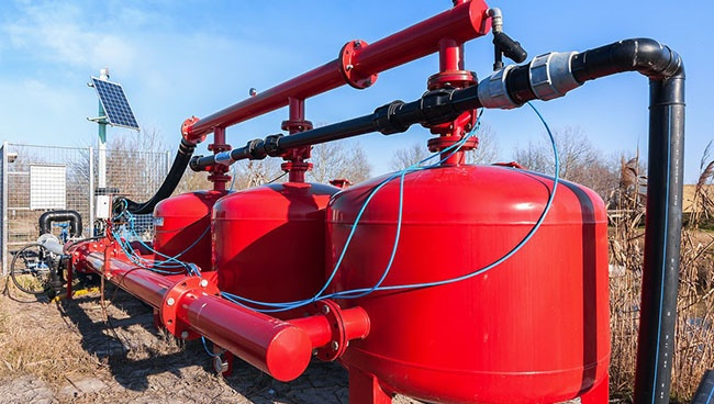
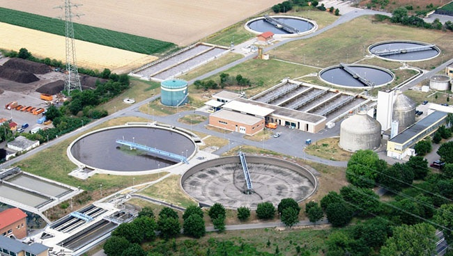
4.1 Pumps
Pumps are one of the most common and energy-intensive applications for VFDs. In many systems, demand for fluid flow or pressure fluctuates significantly.
- Water and Wastewater Treatment: VFDs are crucial for controlling the flow rates of pumps in municipal water supply, sewage systems, and treatment plants. They ensure consistent water pressure across distribution networks, optimize aeration processes, and reduce energy consumption by preventing over-pumping.
- HVAC Chilled Water Systems: In commercial buildings, VFDs regulate the speed of chilled water pumps, adjusting the flow to meet actual cooling demands, leading to substantial energy savings.
- Irrigation Systems: VFDs optimize water delivery in agricultural irrigation, matching pump output to crop needs and soil conditions, conserving water and energy.
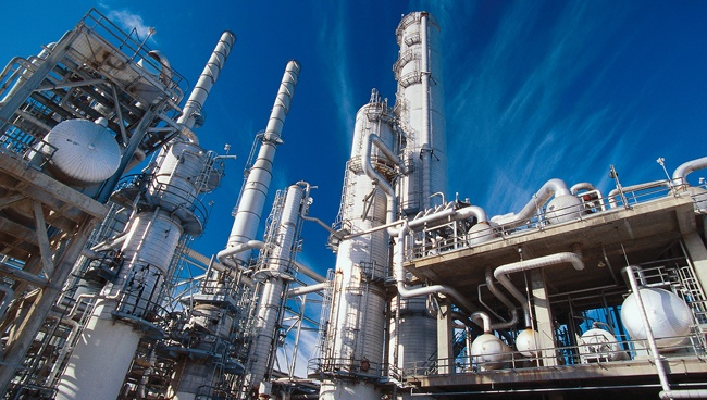
- Industrial Process Pumping: From chemicals and pharmaceuticals to food and beverage, VFDs precisely control the flow and pressure of liquids in various manufacturing processes, improving product consistency and reducing waste.
4.2 Fans and Blowers
Similar to pumps, fans and blowers are often oversized for peak demand, but operate at reduced capacity for much of their lives. VFDs provide an ideal solution for efficient airflow control.
- HVAC Air Handling Units (AHUs): VFDs regulate the speed of supply and return fans in AHUs, maintaining precise airflow, temperature, and humidity levels within buildings. This dynamic control significantly reduces energy consumption compared to using mechanical dampers.
- Industrial Ventilation: In factories, mines, and workshops, VFDs control exhaust fans and ventilation systems, adjusting air exchange rates to remove fumes, dust, or heat as needed, ensuring a safe and comfortable working environment while optimizing energy use.
- Boilers and Furnaces: VFDs are used on forced draft (FD) and induced draft (ID) fans to control combustion air and exhaust gas flow, optimizing combustion efficiency and reducing emissions.
4.3 Conveyor Systems
Conveyor belts are ubiquitous in material handling, manufacturing, and logistics. VFDs provide the flexibility needed for efficient and gentle material movement.
- Material Handling: VFDs control the speed of conveyor belts in packaging lines, assembly lines, and warehouses. This allows for smooth acceleration and deceleration, preventing product damage, reducing jams, and synchronizing different sections of a production line.
- Sorting and Packaging: In automated sorting and packaging systems, VFDs enable precise speed adjustments to accommodate different product sizes, weights, and processing rates.
- Mining and Bulk Material Transport: VFDs are vital for starting heavily loaded conveyors smoothly, reducing mechanical stress on belts and gearboxes, and adjusting speed to optimize material flow.
4.4 Compressors
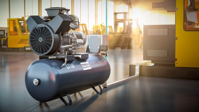
VFDs have revolutionized the efficiency of air compressors, which are traditionally major energy consumers.
- Industrial Air Compressors (Screw and Centrifugal): By matching the compressor's motor speed to the actual demand for compressed air, VFDs eliminate wasteful "unload" cycles and reduce power consumption significantly, especially in applications with fluctuating air requirements.
- Refrigeration Compressors: In refrigeration and chiller systems, VFDs precisely control compressor speed to maintain desired temperatures, leading to substantial energy savings and improved temperature stability.
4.5 HVAC Systems
Beyond just fans and pumps, VFDs play a comprehensive role in optimizing entire Heating, Ventilation, and Air Conditioning (HVAC) systems in commercial, institutional, and even some large residential buildings.
- Chillers and Cooling Towers: VFDs control the motors for chillers, condenser water pumps, and cooling tower fans, adjusting their operation to meet the building's cooling load in real-time, resulting in significant energy savings.
- Overall Building Automation: By integrating with Building Management Systems (BMS), VFDs enable intelligent, demand-driven control of all motor-driven HVAC components, ensuring optimal comfort, air quality, and energy performance.
4.6 Industrial Automation
The precise control offered by VFDs makes them indispensable components in a wide array of industrial automation processes.
- Machine Tools (CNC machines): VFDs control the spindle speed and feed rates of CNC machines, allowing for optimal cutting speeds for various materials and tools, improving machining accuracy and surface finish.
- Mixers and Agitators: In industries like food processing, chemical manufacturing, and pharmaceuticals, VFDs provide precise control over mixing speeds to ensure consistent product quality and prevent over-agitation or settling.
- Extruders: In plastic and metal manufacturing, VFDs regulate the speed of extruder screws, maintaining consistent product dimensions and quality.
- Winding and Unwinding Applications: In textile, paper, and wire industries, VFDs provide tension control for winding and unwinding processes, ensuring smooth operation and preventing material breakage.
These examples highlight how VFDs are not just energy-saving devices, but fundamental tools for improving process control, increasing reliability, and enhancing the overall efficiency of motor-driven systems across virtually all industrial and commercial sectors.
5. Types of VFDs
While all Variable Frequency Drives share the fundamental goal of controlling an AC motor's speed and torque by varying frequency and voltage, they can be categorized based on their input/output characteristics, control methodologies, and the types of motors they are designed to operate. Understanding these distinctions helps in selecting the most appropriate VFD for a given application.
5.1 AC VFDs
The most common and widely used type of VFD is the AC VFD, designed specifically to control AC induction motors. The vast majority of the applications discussed earlier (pumps, fans, conveyors, etc.) utilize AC motors, making AC VFDs the dominant form of drive technology.
- Operation: As detailed in "How a VFD Works," these drives convert incoming AC power to DC, then invert it back to variable frequency and voltage AC power using Pulse Width Modulation (PWM).
- Prevalence: Their high efficiency, robust design, and broad applicability make them the workhorse of industrial motor control. They are available in a vast range of power ratings, from fractional horsepower to megawatts.
- Sub-types: Within AC VFDs, there are further distinctions, primarily related to their control methods (e.g., scalar control, vector control, which we'll discuss next).
5.2 DC VFDs
While AC VFDs dominate the market, DC VFDs (or DC Drives) are designed to control DC motors. Although AC motors have largely supplanted DC motors in many new installations due to their simpler construction and lower maintenance, DC motors and their associated drives still play a crucial role in specific applications.
- Operation: DC drives typically use a rectifier (often an SCR-based bridge) to convert AC input power directly into a variable DC voltage, which then feeds the DC motor's armature and/or field windings. Speed control is achieved by varying the armature voltage, while torque control involves manipulating the field current.
- Applications: DC drives are particularly suited for applications requiring high starting torque, precise low-speed control, and wide speed ranges. They are commonly found in older industrial plants, paper machines, steel mills, cranes, and electric traction systems where their unique torque characteristics are advantageous.
- Advantages: Excellent low-speed torque, simpler control algorithms for certain tasks, and often better performance in regenerative braking (feeding energy back to the line).
- Disadvantages: DC motors require brushes and commutators, leading to more maintenance compared to AC motors.
5.3 Vector Control VFDs (Field-Oriented Control - FOC)
Vector Control VFDs, also known as Field-Oriented Control (FOC) drives, represent a significant advancement in AC motor control. Unlike simpler scalar control (discussed next), vector control treats the AC motor as if it were a DC motor, allowing for independent control of motor flux (which relates to magnetic field strength) and torque-producing current.
- Sophisticated Control: Vector control uses complex mathematical algorithms and advanced processing power to precisely determine the instantaneous position of the motor's rotor flux. It then precisely controls the magnitude and phase of the motor current to independently control torque and speed.
- Encoder or Sensorless: Vector control can be implemented with or without an encoder (a sensor that provides feedback on motor shaft position).
- Closed-Loop Vector Control (with encoder): Offers the highest precision, allowing for exact speed and position control, even at zero speed, and high torque output. Ideal for applications requiring very high accuracy, such as robotics, machine tools, and elevators.
- Sensorless Vector Control: Uses sophisticated algorithms to estimate the rotor position without a physical encoder. While slightly less precise than closed-loop, it provides excellent performance, high starting torque, and a wide speed range, often sufficient for demanding applications without the added cost and complexity of an encoder.
- Key Benefits: Extremely high starting torque, excellent speed regulation across the entire operating range (including very low speeds), fast dynamic response, and precise torque control.
- Applications: Cranes, hoists, extruders, winders, machine tools, test stands, and any application where precise torque and speed control are paramount.
5.4 Scalar Control VFDs (V/f Control)
Scalar Control VFDs, primarily using the Voltage-to-Frequency () control method, are the simplest and most common type of AC VFD. They operate on the principle of maintaining a constant ratio between the applied voltage and frequency to the motor.
- Simpler Operation: The VFD changes the voltage and frequency proportionally to control motor speed. If the frequency is halved, the voltage is also halved. This maintains a relatively constant magnetic flux in the motor, ensuring that the motor can produce sufficient torque.
- Open-Loop Control: Scalar control is inherently an open-loop control method; it does not typically receive feedback from the motor regarding its actual speed or position. It simply outputs a voltage and frequency based on a desired speed reference.
- Key Benefits: Simplicity, cost-effectiveness, ease of setup, and robustness.
- Limitations: Less precise speed regulation compared to vector control, particularly at low speeds. Starting torque might be limited, and dynamic response is not as fast. They can be prone to instability if the load fluctuates significantly.
- Applications: Ideal for applications with fan or pump-like loads (variable torque applications) where precise speed control at very low speeds is not critical. Common in HVAC systems, simple conveyors, small fans, and general-purpose machinery.
The choice between these VFD types hinges on the specific demands of the application, balancing factors like required speed accuracy, torque control, dynamic response, cost, and complexity. Modern VFDs often incorporate both scalar and vector control capabilities, allowing users to select the optimal mode for their specific needs.
6. VFD Installation and Configuration
Proper installation and meticulous configuration are paramount to realizing the full benefits of a Variable Frequency Drive. A poorly installed or incorrectly programmed VFD can lead to inefficient operation, equipment damage, or even safety hazards. This section outlines the key steps involved in deploying a VFD successfully.
6.1 Planning and Preparation
Before any physical installation begins, thorough planning is essential. This stage lays the groundwork for a safe, efficient, and reliable VFD system.
- Site Survey and Environmental Assessment:
- Location: Identify a suitable location for the VFD, considering factors like ambient temperature, humidity, ventilation, dust, and vibration. VFDs generate heat and require adequate airflow for cooling.
- Enclosure: Determine if the VFD requires an additional enclosure (e.g., NEMA 1, 12, 3R, 4X, IP ratings) based on the environmental conditions (indoor/outdoor, wet/dusty environments).
- Altitude: Note the altitude, as higher altitudes can reduce the VFD's derating capacity due to thinner air for cooling.
- Motor and Load Data Collection:
- Gather complete nameplate data for the motor (horsepower/kW, voltage, amperage, RPM, frequency, service factor, insulation class).
- Understand the characteristics of the driven load (e.g., constant torque, variable torque, shock loads, inertia) to ensure proper VFD sizing and parameter settings.
- Power Supply Analysis:
- Assess the incoming power supply voltage, frequency, and available short-circuit current. Ensure it matches the VFD's input requirements.
- Consider potential power quality issues (sags, swells, harmonics from other equipment) that might necessitate input line reactors or filters.
- Cable Sizing and Routing:
- Determine appropriate cable sizes for both input (line side) and output (motor side) power based on VFD and motor current ratings, cable length, and voltage drop considerations.
- Plan cable routing to minimize electromagnetic interference (EMI) between power cables, control cables, and communication cables. Segregation is critical.
- Safety Protocols:
- Establish clear lockout/tagout procedures.
- Ensure compliance with local electrical codes (e.g., NEC in the US, IEC standards in Europe) and safety regulations.
- Identify necessary personal protective equipment (PPE).
6.2 Electrical Wiring and Connections
Correct wiring is critical for the safe and effective operation of the VFD and motor. Errors in this stage can lead to immediate damage or long-term reliability issues.
- Incoming Power Connections: Connect the main power supply to the VFD's input terminals (L1, L2, L3 for three-phase). Ensure proper phase rotation.
- Motor Output Connections: Connect the VFD's output terminals (T1, T2, T3 or U, V, W) to the corresponding motor terminals. Use appropriate motor-rated cable, preferably shielded, to minimize radiated EMI.
- Grounding: Establish a robust grounding system for both the VFD and the motor. Proper grounding is essential for safety, EMI reduction, and surge protection. This often includes a low-impedance ground path back to the service entrance.
- Control Wiring: Connect control signals, such as start/stop commands, speed reference (e.g., 0-10V, 4-20mA), fault relays, and digital inputs/outputs, to the appropriate VFD terminals. Use shielded twisted-pair cables for analog and communication signals to prevent noise interference.
- External Devices: Wire in any external safety circuits (e.g., emergency stop, thermal overload relays if external to VFD), braking resistors, or communication modules as required by the application.
- Disconnection Means: Install appropriate fused disconnects or circuit breakers on the line side of the VFD for isolation and overcurrent protection. Do NOT use a contactor directly between the VFD output and the motor for regular start/stop operations, as this can damage the VFD.
6.3 Parameter Settings and Programming
Once wired, the VFD must be configured (programmed) to match the specific motor and application requirements. This is done via the VFD's keypad, dedicated software, or a human-machine interface (HMI).
- Motor Data Entry: Input crucial motor nameplate data:
- Rated Voltage (V)
- Rated Frequency (Hz)
- Rated Current (A)
- Rated Speed (RPM)
- Rated Power (HP/kW)
- Application-Specific Parameters:
- Acceleration/Deceleration Ramps: Set the time it takes for the motor to ramp up to speed (accel) and ramp down (decel). These values protect the mechanical system and ensure smooth operation.
- Min/Max Frequencies: Define the allowable operating speed range for the motor.
- Control Mode: Select the appropriate control mode (e.g., V/f scalar, sensorless vector, closed-loop vector) based on the application's performance requirements.
- Control Source: Define how the VFD receives its speed reference (e.g., keypad, analog input, communication bus).
- Digital Input/Output Configuration: Program the function of digital inputs (e.g., start, stop, fault reset) and outputs (e.g., run status, fault indication).
- Protection Features: Configure overcurrent, overvoltage, undervoltage, motor overload, and thermal protection settings.
- Skip Frequencies: If mechanical resonance occurs at certain speeds, program the VFD to "skip" these frequencies to prevent vibration.
- Auto-Tuning (if available): Many modern VFDs offer an auto-tuning function. This process allows the VFD to run a series of tests on the connected motor (while disconnected from the load) to accurately determine its electrical characteristics. This optimizes the VFD's control algorithms for that specific motor, leading to better performance and efficiency.
6.4 Commissioning and Testing
The final stage involves bringing the VFD system online and verifying its performance.
- Pre-Power Up Checks:
- Double-check all wiring connections for correctness and tightness.
- Verify grounding integrity.
- Ensure all safety covers are in place.
- Check for any tools or debris left inside the enclosure.
- Initial Power Up: Apply power to the VFD and observe for any immediate fault indications.
- No-Load Test (if feasible): If possible, run the motor without a mechanical load first, gradually increasing speed, to verify basic operation, rotation direction, and current draw.
- Loaded Test: Connect the motor to its mechanical load and perform a full functional test across the operating speed range.
- Monitor motor current, voltage, speed, and temperature.
- Verify acceleration and deceleration times.
- Confirm control inputs (speed reference, start/stop) and outputs (status, fault) are functioning correctly.
- Check for unusual noise, vibration, or overheating.
- Documentation: Record all final parameter settings, wiring diagrams, and test results for future maintenance and troubleshooting.
By diligently following these steps, installers can ensure that the VFD system operates safely, efficiently, and reliably, delivering its intended benefits to the application.
7. VFD Maintenance and Troubleshooting
Even with proper installation and configuration, Variable Frequency Drives require ongoing attention to ensure their reliable and efficient operation. Regular maintenance prevents premature failures, while a systematic approach to troubleshooting can quickly resolve issues and minimize costly downtime.
7.1 Regular Inspection and Cleaning
Preventative maintenance is the cornerstone of VFD longevity. By adhering to a scheduled inspection and cleaning regimen, many common problems can be averted.
- Visual Inspection (Weekly/Monthly):
- External Cleanliness: Check for excessive dust, dirt, or debris on the VFD enclosure, cooling fins, and ventilation openings. Blocked vents significantly impair heat dissipation.
- Connections: Visually inspect all power and control wiring for signs of loose connections, discoloration (indicating overheating), or corrosion. Tight connections are vital.
- Fans: Observe cooling fans (both internal and external) for proper operation, unusual noise, or physical damage. Ensure they are free from obstructions.
- Indicators/Display: Check the VFD's display for any error codes, warning messages, or unusual readings. Note any flickering or blank display.
- Environmental Conditions: Monitor ambient temperature and humidity around the VFD. Ensure the environment remains within the manufacturer's specified operating range. Look for signs of moisture ingress.
- Internal Cleaning (Quarterly/Annually, as per environment):
- De-energize Safely: ALWAYS follow strict lockout/tagout procedures before opening the VFD enclosure. Allow sufficient time for the DC bus capacitors to discharge (check DC bus voltage until it reads zero).
- Dust Removal: Use compressed air (dry, oil-free, and at low pressure to avoid damaging sensitive components) or a soft, non-conductive brush to remove dust and debris from heat sinks, circuit boards, and other internal components. Pay special attention to cooling channels.
- Component Check: Look for swollen or leaking capacitors, discolored components, or burn marks, which can indicate impending failure.
- Filter Replacement/Cleaning: If the VFD or its enclosure has air filters, clean or replace them regularly (e.g., monthly) as they are critical for maintaining proper airflow.
- Component Life Cycle Management: Be aware of the typical lifespan of VFD components. Cooling fans may need replacement every 3-5 years, and DC bus capacitors may require replacement or re-forming (if the VFD has been unpowered for extended periods) every 5-7 years, depending on operating conditions.
7.2 Common VFD Problems and Solutions
Despite diligent maintenance, VFDs can encounter issues. Here are some common problems and their typical solutions:
- Over-current Fault (OC):
- Causes: Sudden load changes, mechanical binding in the driven equipment, motor issues (shorted windings, worn bearings), incorrect VFD acceleration/deceleration times, incorrect motor parameters in the VFD.
- Solutions: Check the mechanical load for obstructions. Inspect the motor. Increase acceleration time. Verify motor parameters. Check for short circuits in motor wiring.
- Over-voltage Fault (OV):
- Causes: Rapid deceleration of a high-inertia load (motor acts as a generator, feeding energy back to the VFD's DC bus), excessively high input voltage, power surges.
- Solutions: Increase deceleration time. Add a braking resistor or braking unit (dynamic braking) if regenerative energy is significant. Check input voltage stability.
- Under-voltage Fault (UV):
- Causes: Low incoming supply voltage, power sag, sudden voltage drop due to heavy loads elsewhere on the grid.
- Solutions: Check the main power supply voltage. Consult the utility company. Install a voltage regulator or uninterruptible power supply (UPS) if frequent sags occur.
- Over-temperature Fault (OH/OT):
- Causes: Insufficient cooling (clogged filters, failed cooling fan), high ambient temperature, VFD enclosure too small, VFD undersized for the application, sustained overload.
- Solutions: Clean filters and cooling fins. Replace faulty cooling fans. Ensure adequate ventilation. Reduce ambient temperature if possible. Verify VFD sizing. Reduce load if consistently overloaded.
- Ground Fault (GF):
- Causes: Insulation breakdown in the motor windings or motor cable, moisture ingress in motor or cables, faulty VFD internal component.
- Solutions: Immediately de-energize and disconnect the motor and cable from the VFD. Use an insulation resistance tester (Megohmmeter) to test the motor and cable for insulation integrity.
- Motor Not Running / Incorrect Speed:
- Causes: Incorrect VFD programming, wrong speed reference, faulty control wiring, motor fault, VFD output fault.
- Solutions: Verify VFD parameters (min/max frequency, control source, motor data). Check control wiring. Test motor winding resistance. Check VFD output voltage and current (using a multimeter and/or oscilloscope).
- Communication Error:
- Causes: Loose communication cables, incorrect communication settings (e.g., baud rate, address), noise interference, faulty communication module.
7.3 Harmonics Mitigation (Continued)
- Active Front End (AFE) VFDs / Active Harmonic Filters: These are the most advanced solutions for harmonic mitigation.
- Active Front End VFDs: Instead of a simple diode rectifier, AFE VFDs use an IGBT-based rectifier that can actively control the input current waveform. This allows them to draw a near-perfect sinusoidal current from the utility, resulting in extremely low harmonic distortion (typically less than 5% THD) and even the ability to regenerate power back to the grid. While more expensive, they are ideal for large installations or facilities with strict power quality requirements.
- Active Harmonic Filters (AHF): These are external devices connected in parallel with the VFD(s) and other harmonic-generating loads. An AHF monitors the current waveform and injects precisely calculated counter-currents to cancel out the harmonic distortions, effectively cleaning up the power line for all connected equipment.
- Passive Harmonic Filters: Tuned LC (inductor-capacitor) filters can be installed on the input side of the VFD to absorb specific harmonic frequencies. They are effective but must be carefully designed for the specific harmonic profile and can lead to resonance issues if not properly applied.
The choice of harmonic mitigation strategy depends on factors such as the total harmonic distortion limits set by the utility (e.g., IEEE 519 standard), the number and size of VFDs, the sensitivity of other equipment on the same electrical network, and the budget.
7.4 Using Diagnostic Tools
Effective troubleshooting relies heavily on the intelligent use of diagnostic tools. These tools provide insights into the VFD's internal state and the motor's performance.
- VFD Keypad and Display: This is the primary and most immediate diagnostic tool.
- Fault Codes: The display will show specific fault codes (e.g., "OC1" for over-current, "OV" for over-voltage) that correspond to entries in the VFD's manual, providing the first clue to the problem.
- Warning Messages: Warnings indicate non-critical conditions that could lead to a fault if not addressed (e.g., "Motor Over-temp Warning").
- Operating Parameters: The display allows monitoring of real-time parameters such as output frequency, output voltage, output current, motor speed (RPM), DC bus voltage, output power (kW), and motor temperature. These readings are invaluable for understanding the VFD's current state.
- Event Logs: Many VFDs maintain an internal log of recent faults and warnings, including timestamps, which helps in identifying intermittent issues or trends.
- Multimeter (Digital Voltmeter/Ammeter): Essential for electrical checks.
- Voltage Checks: Verify incoming AC line voltage, DC bus voltage, and output AC voltage to the motor (measure phase-to-phase and phase-to-ground).
- Current Checks: Measure input and output current to the VFD, and current to the motor. Use a clamp-on ammeter for convenience and safety on live circuits.
- Resistance/Continuity: Check motor winding resistance and cable continuity (with power off and DC bus discharged) to identify open circuits or short circuits.
- Insulation Resistance Tester (Megohmmeter):
- Used to measure the insulation resistance of motor windings and motor cables. A low reading indicates insulation degradation or a ground fault. This is a critical predictive maintenance tool.
- Oscilloscope:
- For advanced troubleshooting, an oscilloscope can be used to visualize the VFD's output waveform (PWM pulses) to the motor. This helps in diagnosing issues like switching problems in the inverter, imbalanced phases, or excessive noise. Caution: Requires specialized knowledge and safety precautions due to high voltages and frequencies.
- VFD Software and PC Interface:
- Many VFD manufacturers provide proprietary software that allows a computer to connect to the VFD. This software typically offers:
- Parameter Management: Easier setting, saving, and loading of parameters.
- Real-time Monitoring: Graphical display of operating data, trending, and logging.
- Diagnostic Tools: Advanced fault diagnostics, waveform analysis, and data logging for detailed troubleshooting.
- Firmware Updates: Ability to update the VFD's internal software.
- Many VFD manufacturers provide proprietary software that allows a computer to connect to the VFD. This software typically offers:
- Thermal Imager (Infrared Camera):
- Useful for identifying overheating components (e.g., loose connections, stressed power components, motor hot spots) on the VFD, motor, or cabling, providing a non-contact method for early detection of potential failures.
By combining regular preventative maintenance with a systematic troubleshooting approach and the judicious use of diagnostic tools, industrial operations can maximize the uptime and lifespan of their VFDs, ensuring continuous productivity.
8. Advanced VFD Features
While the core function of a VFD is to control motor speed, modern Variable Frequency Drives are far more than simple speed controllers. They integrate a host of advanced features that enhance process control, improve efficiency, bolster safety, and facilitate seamless integration into broader automation architectures. These capabilities transform VFDs into intelligent components within industrial systems.
8.1 PID Control
Perhaps one of the most powerful built-in features in many VFDs is their integrated Proportional-Integral-Derivative (PID) control functionality. This allows the VFD to act as a standalone closed-loop controller for various process variables, eliminating the need for an external PLC or dedicated controller in many applications.
- How it Works: The VFD receives feedback from a process sensor (e.g., pressure transducer, flow meter, level sensor) as its "process variable" (PV). It then compares this PV to a desired "setpoint" (SP). The PID algorithm in the VFD calculates the error between the PV and SP and adjusts the motor speed (output frequency) to minimize this error.
- Applications:
- Constant Pressure Pumping: A VFD can maintain a constant water pressure in a building by adjusting pump speed based on feedback from a pressure sensor.
- Constant Flow Systems: Regulating fan or pump speed to maintain a specific airflow or liquid flow rate.
- Temperature Control: Adjusting fan speed in a cooling system to maintain a desired temperature.
- Benefits: Simplified system architecture, reduced hardware costs, faster response times, and more stable process control.
8.2 Braking Resistors
For applications involving high inertia loads or processes requiring rapid deceleration, standard VFDs can generate an over-voltage fault due to the motor acting as a generator and feeding energy back into the VFD's DC bus. Braking resistors (also known as dynamic braking resistors) provide a solution to dissipate this excess regenerative energy.
- How They Work: When the motor decelerates faster than its natural coasting rate, it converts mechanical energy back into electrical energy. The VFD monitors its DC bus voltage; if it rises above a preset limit, it rapidly switches an internal or external transistor to connect the braking resistor across the DC bus. The excess energy is then safely dissipated as heat in the resistor.
- Applications: Cranes, hoists, centrifuges, high-speed saws, large fans or flywheels, and any application where controlled, rapid stopping or deceleration is required.
- Benefits: Enables quick and controlled stops, prevents over-voltage faults, protects the VFD, and improves safety and productivity.
8.3 Communication Protocols (e.g., Modbus, Ethernet/IP)
Modern VFDs are designed to integrate seamlessly into sophisticated industrial automation and Building Management Systems (BMS). This is achieved through the support of various standard communication protocols.
- Purpose: These protocols allow the VFD to communicate with PLCs (Programmable Logic Controllers), HMIs (Human-Machine Interfaces), DCS (Distributed Control Systems), and other network devices. This enables:
- Remote Control: Starting, stopping, and setting speed references from a central control room.
- Monitoring: Reading operational data (current, voltage, speed, power, fault codes) in real-time.
- Parameter Management: Remotely changing VFD parameters.
- Diagnostics: Receiving detailed fault and warning information for predictive maintenance.
- Common Protocols:
- Modbus RTU (RS-485): A widely used, robust serial communication protocol, simple to implement and very common for VFDs.
- Ethernet/IP, PROFINET, Modbus TCP/IP: Increasingly prevalent industrial Ethernet protocols that offer higher speeds, greater data capacity, and easier integration into modern IT networks.
- CANopen, DeviceNet, Profibus DP: Other fieldbus protocols common in specific industries or regions.
- Benefits: Centralized control and monitoring, enhanced diagnostics, reduced wiring complexity, improved data analytics for operational insights, and easier integration into smart factory (Industry 4.0) initiatives.
8.4 Safety Features
Safety is paramount in industrial environments, and VFDs incorporate several features to protect personnel and equipment.
- Safe Torque Off (STO): This is a critical safety function that prevents the VFD from applying power to the motor, even if a run command is present. STO directly cuts the power stage of the VFD, ensuring no unintended motor movement. It is often used for emergency stops or for safe machine access. Many VFDs are certified to meet international safety standards (e.g., IEC 61800-5-2, ISO 13849-1) for STO.
- Safe Stop 1 (SS1): This function initiates a controlled deceleration of the motor to a stop, followed by activation of STO after a defined delay or speed threshold. Useful for applications where a controlled stop is safer than an immediate power cut.
- Integrated Thermal Overload Protection: VFDs constantly monitor the motor's current and can estimate its temperature, providing protection against overheating, often more accurately than traditional thermal overloads.
- Short Circuit and Ground Fault Protection: Internal circuitry protects the VFD and motor from damage due to short circuits or ground faults on the output side.
- Parameter Lockout: The ability to password-protect VFD parameters prevents unauthorized or accidental changes to critical settings.
- Fault Diagnostics: Detailed fault codes and descriptions aid in quickly identifying and resolving safety-related issues.
These advanced features elevate VFDs from mere motor controllers to sophisticated, intelligent, and safe components that significantly enhance the performance, efficiency, and reliability of industrial processes.
9. Selecting the Right VFD
Choosing the appropriate Variable Frequency Drive is a critical decision that impacts system performance, energy efficiency, reliability, and overall cost. A careful evaluation of several key factors is essential to ensure the VFD perfectly matches the application's requirements.
9.1 Motor Compatibility
The VFD and the motor are intrinsically linked, and their compatibility is paramount.
- Motor Type (AC Induction, Permanent Magnet, Synchronous Reluctance): Most VFDs are designed for standard NEMA or IEC AC induction motors, which are the most common industrial motor type. However, for specialized motors like Permanent Magnet (PM) synchronous motors (often found in high-efficiency applications) or Synchronous Reluctance (SynRM) motors, a VFD specifically designed for or capable of controlling these types (usually requiring vector control algorithms) is necessary.
- Voltage and Current Rating: The VFD's output voltage and current ratings must match or exceed the motor's nameplate voltage and full load ampere (FLA) rating. Ensure the VFD can supply the necessary current for the motor's starting and continuous operation.
- Horsepower/kW Rating: While important, simply matching horsepower is insufficient. Always prioritize matching the VFD's continuous output current rating to the motor's FLA, as current is the primary factor for motor heating and VFD sizing.
- Motor Insulation (Inverter Duty): Standard motors are designed for sinusoidal waveforms. The PWM output of a VFD can create voltage spikes and common mode voltages that stress motor winding insulation. For new installations, specify "inverter duty" or "VFD-rated" motors (typically NEMA MG 1 Part 31 or IEC 60034-18-42 compliant) as they have enhanced insulation to withstand these stresses, extending motor life. For existing standard motors, consider adding output filters (e.g., dv/dt filters, sine wave filters) if cable runs are long or insulation integrity is a concern.
- Cable Length: Long motor cable runs (typically over 50-100 feet/15-30 meters, depending on VFD and motor size) can exacerbate voltage reflection issues, leading to higher voltage spikes at the motor terminals. Output reactors or filters may be required.
9.2 Load Requirements
Understanding the characteristics of the driven load is crucial for proper VFD sizing and feature selection.
- Load Type (Variable Torque, Constant Torque, Constant Power):
- Variable Torque: Applications like centrifugal pumps and fans where torque requirements decrease significantly with speed. These are the most energy-efficient VFD applications. A standard VFD sized for the motor's FLA is usually sufficient.
- Constant Torque: Applications where torque remains relatively constant regardless of speed, such as conveyors, positive displacement pumps, and extruders. These often require a VFD with a higher overload capacity and potentially vector control for better low-speed torque.
- Constant Power (Field Weakening): Applications like spindle drives on machine tools where torque decreases at higher speeds (above base speed), but power output remains relatively constant. These require a VFD capable of field weakening.
- Starting Torque and Overload Capacity: Does the application require high starting torque (e.g., a heavily loaded conveyor, mixer)? The VFD must be able to deliver sufficient peak current during acceleration. Consider the VFD's short-term overload rating (e.g., 150% for 60 seconds).
- Speed Range and Accuracy: What is the required minimum and maximum operating speed? Does the application demand precise speed regulation, especially at low speeds or under varying loads (e.g., machine tools, hoists)? If so, vector control (sensorless or closed-loop with encoder feedback) will be necessary.
- Dynamic Response: How quickly must the motor respond to changes in speed or load? Applications requiring rapid acceleration/deceleration or frequent reversals might need VFDs with advanced control algorithms and potentially braking resistors.
- Regenerative Energy: Does the load frequently decelerate rapidly or have overhauling characteristics (e.g., cranes, centrifuges)? If so, the VFD must handle regenerative energy, possibly requiring braking resistors or an Active Front End (AFE) VFD.
9.3 Environmental Conditions
The operating environment significantly influences the type of VFD enclosure and protective features required.
- Ambient Temperature: VFDs are rated for specific ambient temperature ranges (e.g., 0-40°C or 32-104°F). Operating outside this range requires derating or additional cooling. High temperatures severely reduce component lifespan.
- Humidity: High humidity can lead to condensation and corrosion. Ensure the VFD has an appropriate NEMA/IP rating for the humidity level.
- Dust, Dirt, and Contaminants: A dusty or dirty environment requires a higher NEMA/IP rated enclosure (e.g., NEMA 12, IP54, IP65) to prevent contaminants from entering the VFD and causing damage or overheating. Washdown applications may need NEMA 4X/IP66.
- Altitude: At higher altitudes, air density decreases, reducing the cooling efficiency of the VFD. VFDs typically need to be derated for installations above 1000 meters (3300 feet).
- Vibration and Shock: In environments with significant vibration, ensure the VFD is mounted securely and consider vibration-dampening measures.
9.4 Cost Considerations
While initial purchase price is a factor, the total cost of ownership is a more accurate measure of a VFD's economic impact.
- Initial Purchase Price: Compare VFD prices from different manufacturers, but don't let this be the sole deciding factor.
- Energy Savings: Calculate potential energy savings over the lifespan of the equipment. For variable torque loads, payback periods can be very short.
- Installation Costs: Consider wiring, conduit, enclosure, and labor costs.
- Maintenance and Downtime Costs: Factor in expected maintenance requirements, spare parts availability, and the cost of potential downtime if the VFD fails.
- Harmonics Mitigation Costs: If power quality is a concern, include the cost of line reactors, filters, or AFE VFDs.
- Integration Costs: Account for the cost of communication modules, programming time, and integration with existing control systems.
- Rebates and Incentives: Check for local utility rebates or government incentives for energy-efficient equipment, which can significantly offset the initial investment.
By systematically evaluating these factors, engineers and plant managers can make an informed decision, selecting a Variable Frequency Drive that not only meets the technical demands of the application but also delivers optimal performance, reliability, and long-term economic value.
10. Top VFD Manufacturers
The global market for Variable Frequency Drives is highly competitive, dominated by a few large multinational corporations known for their extensive product portfolios, robust technology, and widespread support networks. These manufacturers continuously innovate, offering drives with advanced features, improved efficiency, and enhanced connectivity. While this list is not exhaustive, it highlights some of the most recognized and widely adopted VFD brands worldwide.
10.1 ABB
ABB (Asea Brown Boveri) is a Swiss-Swedish multinational corporation renowned for its leadership in robotics, power, heavy electrical equipment, and automation technology. ABB is one of the largest and most prominent manufacturers of VFDs globally.
- Key Strengths:
- Comprehensive Range: Offers an incredibly broad spectrum of VFDs, from micro drives for small applications to high-power industrial drives for large motors (up to megawatts).
- Application-Specific Drives: Known for specialized drives tailored for specific industries, such as HVAC, water & wastewater, and oil & gas.
- Advanced Features: Strong focus on energy efficiency, connectivity (IoT-enabled drives), and advanced control algorithms.
- Global Presence: Extensive sales and service network worldwide.
- Notable Product Lines: ACS (e.g., ACS355, ACS580, ACH580 for HVAC, ACS880 industrial drives).
10.2 Siemens
Siemens AG is a German multinational conglomerate corporation and the largest industrial manufacturing company in Europe, with a focus on electrification, automation, and digitalization. Siemens is a major player in the VFD market, particularly for industrial automation solutions.
- Key Strengths:
- Integration with Automation: VFDs are seamlessly integrated into the broader Siemens TIA Portal (Totally Integrated Automation) ecosystem, simplifying system design and programming.
- Robustness and Reliability: Known for producing highly reliable and durable drives suitable for demanding industrial environments.
- Wide Performance Range: Offers drives from basic to high-performance, including specialized drives for motion control.
- Industry-Specific Solutions: Strong presence in automotive, machine building, and process industries.
- Notable Product Lines: SINAMICS (e.g., G120, G130, S120 series).
10.3 Rockwell Automation (Allen-Bradley)
Rockwell Automation is an American provider of industrial automation and information products. Its Allen-Bradley brand is highly recognized for control systems and industrial components, including a significant line of VFDs.
- Key Strengths:
- Integration with Logix Platform: Strong integration with Rockwell's ControlLogix and CompactLogix PLCs, simplifying programming and data exchange through the Studio 5000 environment.
- User-Friendly Interface: Often praised for intuitive programming and diagnostic capabilities, especially for users familiar with Rockwell's ecosystem.
- Robustness: Products are generally designed for demanding industrial applications.
- North American Market Share: Very strong market presence in North America.
- Notable Product Lines: PowerFlex (e.g., PowerFlex 525, PowerFlex 755 series).
10.4 Danfoss
Danfoss A/S is a Danish multinational company focused on climate and energy efficiency solutions. They are a significant global supplier of VFDs, particularly strong in HVAC, refrigeration, and water & wastewater applications.
- Key Strengths:
- Energy Efficiency Focus: Pioneering in VFD technology with a strong emphasis on maximizing energy savings.
- Dedicated Application Expertise: Excellent application-specific software and features for pumps, fans, and refrigeration compressors.
- User Interface: Often lauded for their user-friendly keypads and setup wizards.
- Compact Designs: Known for compact and modular designs.
- Notable Product Lines: VLT® Drives (e.g., VLT® HVAC Drive, VLT® AQUA Drive, VLT® AutomationDrive).
10.5 Schneider Electric
Schneider Electric is a French multinational corporation providing energy management and automation solutions worldwide. They offer a broad portfolio of industrial control and power products, including VFDs.
- Key Strengths:
- Comprehensive Offerings: Provides a wide range of VFDs suitable for various applications, from simple machines to complex processes.
- EcoStruxure Integration: Drives are part of Schneider's broader EcoStruxure architecture for connected products and edge control, facilitating smart energy management.
- Strong Presence in Infrastructure and Buildings: Particularly strong in commercial buildings, data centers, and critical infrastructure.
- User-Friendly Tools: Emphasis on ease of use and commissioning.
- Notable Product Lines: Altivar (e.g., Altivar Process, Altivar Machine, Altivar Easy series).
10.6 Yaskawa
Yaskawa Electric Corporation is a Japanese manufacturer of servomotors, motion controllers, AC motor drives, switches, and industrial robots. They are a leading global producer of VFDs, particularly known for their high-performance and reliable drives.
- Key Strengths:
- High Performance: Renowned for drives that offer excellent speed and torque control, especially in demanding applications.
- Quality and Reliability: Products are known for their robust build quality and long lifespan.
- Motion Control Expertise: Deep experience in motion control, which translates into superior drive performance for precise applications.
- Broad Industry Reach: Used across various industries, including material handling, machine tools, and general industrial applications.
- Notable Product Lines: A1000, P1000, V1000, J1000 series.
These manufacturers continue to push the boundaries of VFD technology, offering increasingly intelligent, efficient, and connected solutions that meet the evolving demands of modern industry.
11. Future Trends in VFD Technology
The landscape of industrial automation and energy management is continuously evolving, and Variable Frequency Drive technology is at the forefront of this transformation. Driven by demands for greater efficiency, intelligence, and connectivity, VFDs are becoming more sophisticated, integrated, and predictive. The future of VFDs points towards devices that are not just controllers, but active participants in smart, sustainable, and highly optimized industrial ecosystems.
11.1 Smart VFDs and IoT Integration
The convergence of VFD technology with the Industrial Internet of Things (IIoT) is rapidly giving rise to "smart VFDs." These intelligent drives are equipped with enhanced processing power, built-in sensors, and advanced communication capabilities, allowing them to participate actively in connected environments.
- Real-time Data and Analytics: Smart VFDs will continuously collect a wealth of operational data – not just motor current and speed, but also internal temperature, vibration, power quality, and even motor health indicators. This data can be transmitted wirelessly or via industrial Ethernet protocols (e.g., Modbus TCP/IP, Ethernet/IP, PROFINET) to cloud-based platforms or local edge devices for real-time analysis.
- Remote Monitoring and Control: Operators and maintenance personnel will increasingly be able to monitor and control VFDs remotely from any location, receiving alerts, adjusting parameters, and diagnosing issues without needing to be physically present at the drive.
- AI and Machine Learning Integration: Future VFDs will leverage Artificial Intelligence (AI) and Machine Learning (ML) algorithms. These algorithms can analyze historical and real-time data to:
- Optimize Performance: Continuously fine-tune VFD parameters based on changing load conditions, environmental factors, or energy prices to achieve maximum efficiency.
- Identify Anomalies: Detect subtle deviations from normal operation that could indicate impending faults.
- Adaptive Control: Learn from past operations and adapt control strategies for improved stability and response.
- Edge Computing: More processing power will be embedded directly into the VFD (edge computing), allowing for immediate data analysis and decision-making at the device level, reducing reliance on cloud connectivity for critical functions.
11.2 Enhanced Energy Efficiency
While VFDs are already synonymous with energy savings, ongoing advancements are pushing the boundaries of efficiency even further.
- Wide Bandgap Semiconductors (SiC, GaN): The adoption of Silicon Carbide (SiC) and Gallium Nitride (GaN) semiconductors is a game-changer. These "wide bandgap" materials offer superior electrical properties compared to traditional silicon-based power components. They can:
- Operate at higher switching frequencies, enabling smaller VFD designs and smoother motor current waveforms.
- Handle higher temperatures and voltages, improving robustness.
- Significantly reduce power losses within the VFD itself, leading to higher overall system efficiency.
- Advanced Motor Control Algorithms: Continued development of more sophisticated vector control and direct torque control (DTC) algorithms will allow VFDs to achieve even higher precision, better low-speed torque, and improved efficiency across wider operating ranges, especially for new motor technologies like SynRM.
- Integrated Power Quality Solutions: Future VFDs will increasingly integrate active front-end (AFE) technology or advanced harmonic filtering directly into their design, providing ultra-low harmonic distortion and often regenerative braking capabilities, further enhancing overall energy efficiency and power quality.
- System-Level Optimization: Beyond individual VFD efficiency, there will be a greater focus on optimizing entire motor-driven systems, including the motor, VFD, and mechanical load, through intelligent control strategies and data-driven insights.
11.3 Predictive Maintenance
The integration of IoT and AI capabilities positions VFDs as critical enablers of predictive maintenance strategies. This shifts maintenance from a reactive (fix-it-when-it-breaks) or time-based (scheduled regardless of condition) approach to a condition-based approach, anticipating failures before they occur.
- Continuous Condition Monitoring: Smart VFDs will constantly monitor key parameters of both the drive and the connected motor (current, voltage, temperature, vibration, power factor, etc.).
- Anomaly Detection: AI/ML algorithms will analyze these data streams to detect subtle anomalies or deviations from normal operating patterns that indicate potential issues. For example, a slight increase in motor current at a given speed, or a subtle change in VFD heat sink temperature, could signal a degrading bearing or clogged filter.
- Proactive Alerts and Recommendations: When an anomaly is detected, the VFD can generate an alert, notifying maintenance personnel. More advanced systems will even provide recommendations for troubleshooting steps or parts replacement, based on historical data and failure patterns.
- Optimized Maintenance Schedules: By knowing precisely when maintenance is needed, facilities can optimize their maintenance schedules, reducing unnecessary interventions, minimizing downtime, extending the lifespan of equipment, and lowering overall maintenance costs.
In essence, VFDs are evolving from isolated components into interconnected, intelligent nodes within the broader digital industrial ecosystem. This evolution promises not only greater energy savings and process optimization but also a more resilient, responsive, and autonomous manufacturing future.
Conclusion
The Variable Frequency Drive (VFD) has evolved from a specialized motor control device into an indispensable cornerstone of modern industrial and commercial operations. Its fundamental ability to precisely regulate the speed and torque of AC motors by varying frequency and voltage has unlocked a cascade of benefits that are driving efficiency, productivity, and sustainability across countless sectors.
12.1 Recap of VFD Benefits
As we've explored throughout this article, the advantages of adopting VFD technology are multifaceted and compelling:
- Unparalleled Energy Efficiency and Cost Savings: By allowing motors to operate only as fast as necessary, VFDs dramatically reduce energy consumption, especially in variable-torque applications like pumps and fans, leading to significant and often rapid returns on investment. This directly translates to lower operational costs and a reduced carbon footprint.
- Precise Motor Speed and Torque Control: VFDs provide granular control over motor performance, enabling fine-tuning of processes, consistent product quality, and optimized throughput across a wide range of applications.
- Extended Motor and Equipment Life: The soft starting and stopping capabilities of VFDs eliminate mechanical shock and reduce electrical stress, mitigating wear and tear on motors, gearboxes, belts, and other connected machinery. This leads to fewer breakdowns, lower maintenance costs, and prolonged equipment lifespan.
- Reduced Mechanical Stress: Beyond the motor, the entire driven system benefits from the smooth acceleration and deceleration, preventing issues like water hammer in piping systems or jerky movements in conveyors.
- Improved Process Control: Through features like integrated PID control and seamless communication protocols, VFDs enable dynamic and responsive process regulation, maintaining desired setpoints and enhancing overall system stability.
- Enhanced Safety Features: Modern VFDs incorporate critical safety functions like Safe Torque Off (STO) and robust internal protections, contributing to a safer working environment.
12.2 The Future of VFDs in Industry
The journey of the VFD is far from over. As industries embrace digital transformation and the principles of Industry 4.0, Variable Frequency Drives are poised to become even more intelligent, connected, and indispensable. The ongoing integration of IoT capabilities, advanced AI and machine learning algorithms, and next-generation semiconductor technologies (like SiC and GaN) will transform VFDs into sophisticated data hubs and active participants in smart factories. This evolution will lead to:
- Hyper-Optimized Operations: VFDs that continuously learn and adapt to optimize energy usage, process parameters, and predictive maintenance schedules.
- Seamless Integration: Drives that are effortlessly integrated into broader automation and cloud-based systems, providing real-time insights and remote control from anywhere.
- Enhanced Sustainability: Even greater energy savings, reduced waste, and a smaller environmental impact as VFDs become even more efficient and enable regenerative capabilities.
In conclusion, the Variable Frequency Drive is more than just a piece of electrical equipment; it is a vital enabler of modern industrial efficiency, control, and sustainability. Its proven benefits and exciting future developments ensure its continued role as a foundational technology in shaping the smarter, greener, and more productive industries of tomorrow.
Previous Post
VFDs: The Key to Energy Savings and Motor Control
Next Post
Understanding Soft Starters: A Comprehensive Guide
Copyright 2024 Fujian Raynen Technology Co.,Ltd. All Rights Reserved.
Privacy Policy  Motor Control Manufacturers