English
 Español
 عربى
عربى


1.Introduction to AC Drives (Variable Frequency Drives) In the realm of modern industrial control an......
READ MOREVFDs: The Key to Energy Savings and Motor Control
Content
- 1 1.Introduction to AC Drives (Variable Frequency Drives)
- 2 2.How AC Drives Work
- 3 3.Key Benefits of Using AC Drives
- 4 4.Applications of AC Drives
- 5 5.Selecting the Right AC Drive
- 5.1 Motor Voltage and Current Requirements
- 5.2 Horsepower Rating (kW Rating)
- 5.3 Application-Specific Requirements (Torque, Speed Range)
- 5.4 Environmental Considerations (Temperature, Humidity, Dust)
- 5.5 Communication Protocols (Modbus, Ethernet/IP, Profinet, etc.)
- 5.6 Enclosure Types (NEMA Ratings / IP Ratings)
- 6 6.Programming and Configuration
- 7 7.Installation and Wiring
- 8 8.Maintenance and Troubleshooting
- 9 9.Advanced Features and Technologies
- 10 10.Safety Considerations
- 11 11.Future Trends in AC Drive Technology
1.Introduction to AC Drives (Variable Frequency Drives)
In the realm of modern industrial control and automation, few technologies have had as profound an impact as the AC drive, often referred to as a Variable Frequency Drive (VFD). These sophisticated electronic devices have revolutionized the way electric motors are controlled, offering unprecedented levels of precision, efficiency, and flexibility. From optimizing energy consumption in large industrial plants to enabling intricate movements in robotic systems, AC drives are an indispensable component of countless applications worldwide.
What is an AC Drive (VFD)?
At its core, an AC drive is a power electronics device that controls the speed and torque of an AC (alternating current) electric motor by varying the frequency and voltage of the electrical power supplied to the motor. Unlike traditional motor control methods that might rely on mechanical means or simple on/off switching, an AC drive provides continuous and precise adjustment of the motor's operating parameters.
The term "Variable Frequency Drive" (VFD) explicitly highlights the primary mechanism of control: altering the frequency of the AC power. Since the synchronous speed of an AC motor is directly proportional to the frequency of the applied voltage and inversely proportional to the number of poles, changing the frequency allows for continuous speed variation. Simultaneously, the drive adjusts the voltage in proportion to the frequency to maintain a constant magnetic flux in the motor, ensuring efficient operation and preventing saturation.
Why are AC Drives Important?
The importance of AC drives stems from several critical advantages they offer over traditional motor control methods:
- Energy Efficiency: This is perhaps the most significant benefit. Many industrial applications, such as pumps and fans, exhibit a "cubic relationship" between speed and power consumption. Even a small reduction in motor speed can lead to substantial energy savings. AC drives enable motors to run only as fast as necessary, drastically cutting down on electricity usage and operational costs.
- Precise Control: AC drives provide unparalleled control over motor speed, acceleration, deceleration, and even torque. This precision is crucial for processes requiring exact movement, such as conveyor systems, machine tools, and robotics.
- Improved Process Control: By precisely regulating motor speed, AC drives contribute to better product quality, reduced waste, and more consistent output in manufacturing and processing plants.
- Reduced Mechanical Stress: Soft starting and stopping capabilities, inherent to AC drives, eliminate the sudden jolts and high inrush currents associated with direct-on-line (DOL) starting. This significantly reduces mechanical stress on the motor, gears, bearings, and the driven equipment, leading to extended lifespan and reduced maintenance.
- Extended Motor Lifespan: Beyond reducing mechanical stress, AC drives also offer protection features against overcurrent, overvoltage, undervoltage, and overheating, further contributing to the longevity of the motor.
Brief History and Evolution of AC Drives
The concept of varying the frequency to control AC motor speed isn't new, but its practical implementation was challenging until the advent of power electronics. Early attempts involved cumbersome motor-generator sets.
The real breakthrough came with the development of thyristors (SCRs) in the mid-20th century, which allowed for the first electronic variable frequency drives. However, these early drives were large, inefficient, and often limited in their control capabilities.
The 1970s and 80s saw significant advancements with the introduction of Gate Turn-Off (GTO) thyristors and later Insulated Gate Bipolar Transistors (IGBTs). IGBTs, in particular, revolutionized AC drive technology due to their high switching speeds, lower losses, and ease of control. This enabled the development of more compact, efficient, and sophisticated drives capable of using techniques like Pulse Width Modulation (PWM) to generate near-sinusoidal output waveforms.
Today, AC drives are highly integrated, intelligent devices incorporating advanced microprocessors, sophisticated control algorithms (like vector control and direct torque control), and communication capabilities. They continue to evolve, becoming smaller, more powerful, more energy-efficient, and increasingly integrated into the broader landscape of industrial IoT (Internet of Things) and smart manufacturing. This continuous evolution underscores their vital role in shaping the future of industrial automation and energy management.
2.How AC Drives Work
To truly appreciate the power and versatility of AC drives, it's essential to understand the fundamental principles behind their operation. While the internal electronics can be complex, the core process involves converting incoming AC power into DC, and then converting it back into variable-frequency, variable-voltage AC power tailored for the motor. This conversion happens in several distinct stages:
Basic Components of an AC Drive
Most AC drives, regardless of their size or complexity, share a common architecture comprising four main stages:
- Rectifier Stage: Converts incoming fixed-frequency, fixed-voltage AC power to DC power.
- DC Bus (or DC Link): Stores and smooths the DC voltage from the rectifier.
- Inverter Stage: Converts the DC power from the bus back into variable-frequency, variable-voltage AC power for the motor.
- Control Circuitry: The "brain" of the drive, responsible for managing all the other stages, monitoring inputs, and executing control algorithms.
Rectifier Stage: Converting AC to DC
The first step in an AC drive's operation is to transform the incoming AC line voltage into a DC voltage. This is typically achieved using a diode bridge rectifier.
- For single-phase drives, a full-wave bridge rectifier with four diodes is used.
- For three-phase drives, a six-diode bridge rectifier is common, rectifying all three phases of the incoming AC supply.
The output of the rectifier is a pulsating DC voltage. While some high-performance or specialized drives might use active front-end (AFE) rectifiers (which can also feed energy back to the grid and reduce harmonics), the basic diode rectifier is the most prevalent for its simplicity and cost-effectiveness.
DC Bus: Smoothing the DC Voltage
Following the rectifier, the pulsating DC voltage enters the DC bus, also known as the DC link. This stage primarily consists of large capacitors. These capacitors serve several critical functions:
- Smoothing the DC Voltage: They filter out the ripple from the rectified DC, providing a relatively smooth and stable DC voltage for the inverter stage.
- Energy Storage: They act as an energy reservoir, providing instantaneous current to the inverter during sudden load changes and absorbing regenerative energy from the motor during deceleration.
- Voltage Boosting (Optional): In some designs, particularly for drives operating on lower input voltages, an optional DC-DC converter might be present here to boost the voltage.
The voltage on the DC bus is typically higher than the peak of the incoming AC line voltage (e.g., for a 400V AC input, the DC bus voltage will be around 540-560V DC).
Inverter Stage: Converting DC to Variable Frequency AC
This is the most dynamic and critical stage of the AC drive. The inverter takes the smooth DC voltage from the DC bus and converts it back into AC power with variable voltage and, crucially, variable frequency. Modern inverters primarily use Insulated Gate Bipolar Transistors (IGBTs) as high-speed electronic switches.
The IGBTs are arranged in a specific configuration (typically six IGBTs for a three-phase output) and are rapidly switched on and off in a precise sequence. By controlling the timing and duration of these switching actions, the inverter can synthesize an AC waveform.
Control Circuitry: The Brain of the Drive
The control circuitry is the intelligence behind the AC drive. It's typically composed of a powerful microprocessor or digital signal processor (DSP) along with associated memory, input/output (I/O) ports, and communication interfaces. This circuitry performs several vital functions:
- Receiving Commands: It interprets commands from operators (via keypads, HMIs), PLCs, or other control systems (e.g., speed reference, start/stop commands).
- Monitoring Feedback: It continuously monitors motor current, voltage, temperature, and sometimes speed (if an encoder is used) to ensure safe and optimal operation.
- Executing Control Algorithms: Based on the desired speed and torque, it calculates the precise switching patterns for the IGBTs in the inverter.
- Protection: It implements various protection features against faults like overcurrent, overvoltage, undervoltage, overheating, and motor overload.
- Communication: It manages communication with external systems using various industrial protocols.
PWM (Pulse Width Modulation) Technique
The primary technique used by the control circuitry to create the variable frequency and voltage AC output from the DC bus is Pulse Width Modulation (PWM). Here's how it works:
- Fixed DC Voltage: The inverter receives a fixed DC voltage from the DC bus.
- Rapid Switching: The IGBTs in the inverter are rapidly switched on and off at a very high frequency (the "carrier frequency," typically several kilohertz).
- Varying Pulse Width: Instead of varying the DC voltage directly, the control circuitry varies the width of the ON-time pulses for the IGBTs.
- Synthesizing AC:
- To create a higher voltage (RMS average), the pulses are made wider (IGBTs are "ON" for a longer duration).
- To create a lower voltage, the pulses are made narrower.
- To create a higher frequency, the sequence of pulses is repeated more rapidly.
- To create a lower frequency, the sequence of pulses is repeated less rapidly.
By precisely modulating the width and frequency of these DC pulses, the inverter synthesizes a series of "chopped" DC voltage pulses that, when fed to the inductive motor windings, approximate a smooth sinusoidal AC waveform. The motor's inductance acts as a natural filter, smoothing out these pulses and allowing the motor to respond as if it's receiving a true sine wave, albeit with some harmonic content.
3.Key Benefits of Using AC Drives
The widespread adoption of AC drives isn't merely a technological trend; it's a direct result of the significant and tangible benefits they offer across a vast spectrum of industrial and commercial applications. These advantages often translate directly into reduced operational costs, improved productivity, and enhanced system reliability.
Energy Efficiency and Cost Savings
This is arguably the most compelling benefit of AC drives, especially for applications involving variable torque loads like pumps, fans, and compressors.
- Optimized Energy Consumption: Unlike traditional methods where motors run at full speed regardless of demand (often wasting energy through throttling valves or dampers), AC drives allow the motor speed to precisely match the load requirements. For centrifugal loads, power consumption is proportional to the cube of the speed (). This means even a small reduction in speed can lead to dramatic energy savings. For example, reducing motor speed by just 20% can result in approximately 50% energy savings.
- Reduced Peak Demand: Soft starting capabilities (discussed below) reduce the high inrush currents associated with direct-on-line (DOL) starts, which helps in managing peak electricity demand charges.
- Government Incentives: Many regions offer incentives or rebates for businesses that implement energy-efficient technologies like AC drives, further enhancing the return on investment.
These energy savings directly translate into significant reductions in operational costs over the lifespan of the equipment, often leading to very quick payback periods for the drive investment.
Precise Motor Speed Control
One of the fundamental functions of an AC drive is its ability to precisely control the rotational speed of the motor.
- Infinite Speed Variation: Unlike multi-speed motors or mechanical gearboxes that offer discrete speed steps, AC drives provide continuous, stepless speed control from virtually zero RPM up to and sometimes beyond the motor's rated speed.
- Accuracy and Repeatability: Modern drives, especially those utilizing advanced control methods like vector control, can maintain speed with high accuracy, even under varying load conditions. This is critical for processes requiring exact timing and positioning.
Improved Process Control
The ability to precisely control motor speed has a direct and profound impact on overall process performance.
- Enhanced Product Quality: In applications like extruders, mixers, or web handling, consistent and controlled speed leads to uniform product quality, fewer defects, and reduced scrap.
- Optimized Throughput: Processes can be finely tuned to maximize production rates without compromising quality or stressing equipment.
- Reduced Noise and Vibration: By operating motors at optimal speeds, AC drives can minimize mechanical noise and vibration, contributing to a more stable and comfortable operating environment.
- Closed-Loop Control: When integrated with sensors and PID controllers (often built into the drive), AC drives can automatically adjust motor speed to maintain setpoints for parameters like pressure, flow, temperature, or liquid level.
Reduced Mechanical Stress on Motors and Equipment
Direct-on-line starting of electric motors creates significant mechanical and electrical stresses. AC drives mitigate these issues effectively.
- Soft Starting and Stopping: Instead of instantly applying full voltage, an AC drive gradually ramps up the voltage and frequency, allowing the motor to accelerate smoothly. Similarly, it can decelerate the motor smoothly. This eliminates the sudden shock loading on mechanical components (gearboxes, couplings, belts, bearings) and the motor windings themselves.
- Reduced Torque Spikes: The smooth acceleration avoids high torque spikes that can damage driven machinery.
Extended Motor Lifespan
By reducing mechanical stress and providing comprehensive protection, AC drives contribute significantly to the longevity of electric motors and associated equipment.
- Lower Operating Temperatures: Running motors at optimized speeds and without excessive current surges reduces heat generation, which is a major factor in motor insulation degradation.
- Protection Features: AC drives incorporate numerous protective functions such as:
- Overcurrent protection: Prevents damage from excessive motor current.
- Overvoltage/Undervoltage protection: Shields the drive and motor from line voltage fluctuations.
- Motor Overload protection: Prevents the motor from operating beyond its thermal limits.
- Phase loss protection: Detects and reacts to missing input or output phases.
- Stall prevention: Prevents the motor from stalling and drawing excessive current.
- Ground fault protection: Detects current leakage to ground.
These features prevent catastrophic failures, reduce unscheduled downtime, and extend the operational life of valuable assets.
Soft Starting and Stopping Capabilities
As mentioned, this is a distinct and highly valuable benefit.
- Smooth Acceleration: The drive controls the rate at which the motor speeds up, allowing for a gradual, controlled increase in speed. This is crucial for applications involving delicate materials, liquids that could slosh, or systems where sudden movements are undesirable.
- Smooth Deceleration: Similarly, the drive can bring the motor to a controlled stop, preventing mechanical shock and ensuring a smooth transition. This is particularly useful in high-inertia applications or where precise stopping is required.
- Elimination of Inrush Current: Direct-on-line motors draw a very high inrush current (typically 6-8 times their full-load current) at startup. AC drives eliminate this by gradually increasing current, which reduces stress on the electrical supply system, circuit breakers, and cables.
In summary, the benefits of AC drives extend far beyond simple speed control, encompassing significant energy savings, enhanced operational efficiency, reduced maintenance, and prolonged equipment life, making them a cornerstone of modern industrial automation and energy management strategies.
4.Applications of AC Drives
The versatility and numerous benefits of AC drives have led to their pervasive adoption across virtually every industrial and commercial sector. Their ability to precisely control motor speed and torque makes them indispensable for optimizing processes, saving energy, and enhancing system reliability in a diverse array of applications.
Pumps, Fans, and Compressors
This category represents one of the largest and most impactful applications for AC drives, primarily due to the significant energy savings they provide.
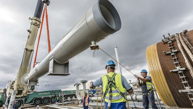
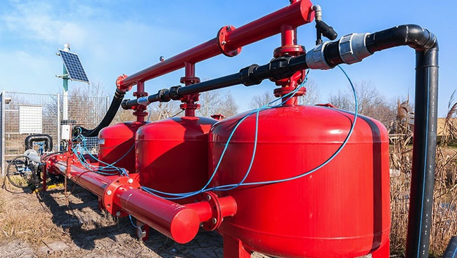
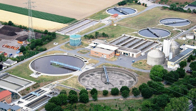
- Pumps: In water treatment plants, HVAC systems, and industrial fluid transfer, pumps often operate under varying demand. Instead of using mechanical throttling valves to reduce flow (which wastes energy by maintaining full pump speed), an AC drive adjusts the pump motor speed to deliver precisely the required flow or pressure. This results in substantial energy savings, reduced wear on valves and piping, and better pressure regulation.
- Fans: Similar to pumps, industrial fans and blowers (e.g., in ventilation systems, air handlers, cooling towers) benefit immensely from variable speed control. By slowing down the fan when less airflow is needed, AC drives dramatically reduce energy consumption and noise levels.
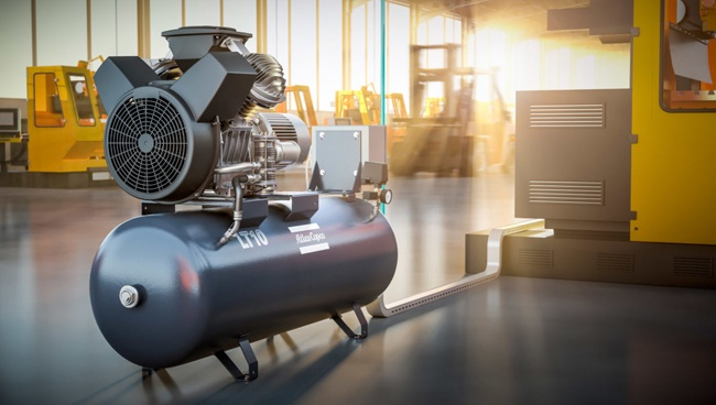
- Compressors: In compressed air systems, AC drives can match the compressor's output to the air demand, preventing constant loading/unloading cycles or blow-off, thereby saving energy and reducing wear on the compressor components.
Conveyor Systems
AC drives are fundamental to the efficient operation of conveyor systems in manufacturing, logistics, and material handling.
- Controlled Start/Stop: Soft starting and stopping protect valuable products from jarring movements and reduce stress on belts, gears, and motors, extending equipment life.
- Variable Speed for Throughput: Speed can be precisely adjusted to match production rates, different product types, or specific process steps. This ensures smooth material flow and prevents bottlenecks.
- Load Balancing: In multi-motor conveyor systems, AC drives can be coordinated to share the load evenly, preventing one motor from becoming overloaded.
HVAC Systems
Heating, Ventilation, and Air Conditioning (HVAC) systems in commercial buildings, hospitals, and industrial facilities are major energy consumers. AC drives play a crucial role in optimizing their efficiency.
- Variable Air Volume (VAV) Systems: Drives on supply and return fans allow airflow to be precisely controlled based on building demand, rather than operating fans at full speed all the time.
- Chiller Pumps and Cooling Towers: Optimizing the speed of pumps for chilled water and condenser water, as well as cooling tower fans, leads to significant energy savings and improved temperature regulation.
- Improved Comfort: Precise control over airflow and water flow contributes to more stable and comfortable indoor environments.
Industrial Automation
AC drives are at the heart of many automated manufacturing processes, providing the motion control necessary for precision and synchronization.
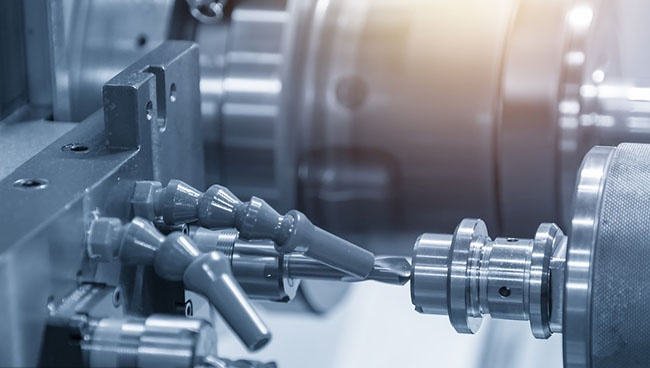
- Machine Tools: From CNC machines to lathes and milling machines, AC drives provide precise spindle speed control and accurate axis positioning.
- Robotics: Highly dynamic and accurate control of robot joints requires sophisticated motor control, often delivered by specialized AC servo drives.
- Packaging Machinery: Synchronized movements of conveyors, fillers, sealers, and labelers are critical for efficient packaging lines, all enabled by coordinated AC drives.
- Textile Machinery: Precise control of yarn tension and fabric speed is essential for quality production, making AC drives invaluable in this sector.
Renewable Energy Systems (Wind Turbines, Solar Power)
AC drive technology is integral to harnessing and converting renewable energy sources into usable electricity.
- Wind Turbines: In modern variable-speed wind turbines, AC drives (or converters) are used to convert the variable frequency output of the generator (which changes with wind speed) into a fixed grid frequency (e.g., 50 Hz or 60 Hz). This maximizes energy capture across a range of wind conditions.
- Solar Power (PV Inverters): While often called "inverters," these devices fundamentally perform a similar function to an AC drive's inverter stage – converting the DC output from solar panels into grid-compatible AC power. Many also include features for maximum power point tracking (MPPT) to optimize energy harvest.
Electric Vehicles (EVs)
The rapidly expanding market for electric vehicles relies heavily on advanced AC drive technology.
- Traction Inverters: The "motor controller" or "traction inverter" in an EV is essentially a sophisticated AC drive. It converts the DC power from the battery pack into variable-frequency, variable-voltage AC power to drive the electric traction motor.
- Regenerative Braking: AC drives enable regenerative braking, where the electric motor acts as a generator during deceleration, converting kinetic energy back into electrical energy to recharge the battery, significantly improving efficiency and range.
- Precise Control: Drives provide smooth acceleration, precise speed control, and efficient power delivery, contributing to the performance and driving experience of EVs.
The sheer breadth of these applications underscores the transformative role AC drives play in enabling efficiency, control, and innovation across a vast array of industries, making them a cornerstone of modern power transmission and automation.
5.Selecting the Right AC Drive
Choosing the appropriate AC drive for a specific application is a crucial step that directly impacts system performance, efficiency, reliability, and overall cost. A mismatch between the drive and the application can lead to poor performance, premature failure, or unnecessary expense. Several key factors must be carefully considered during the selection process.
Motor Voltage and Current Requirements
This is the most fundamental compatibility check. The AC drive's input and output voltage ratings must match the electrical supply and the motor's voltage rating, respectively.
- Input Voltage: Does the drive need to operate on single-phase or three-phase power? What is the nominal line voltage (e.g., 230V, 400V, 480V, 690V AC)?
- Output Voltage: The drive's output voltage range must be compatible with the motor's rated voltage.
- Motor Full Load Amps (FLA): The drive's continuous output current rating must be equal to or greater than the motor's full load amperage. It's often recommended to select a drive with a slightly higher current rating than the motor, especially for demanding applications or those with potential for overload.
Horsepower Rating (kW Rating)
While often used as a primary selection criterion, matching horsepower (HP) or kilowatt (kW) ratings alone isn't always sufficient. It's a good starting point, but current and application type are more critical.
- Standard Match: For general-purpose applications, a drive with the same HP/kW rating as the motor is often selected.
- Derating: Be aware that some manufacturers publish drive ratings based on "constant torque" or "variable torque" loads. For constant torque applications (e.g., conveyors, extruders), the drive might need to be oversized compared to a variable torque application (e.g., fans, pumps) of the same motor HP. Environmental factors (temperature, altitude) can also require derating.
- Service Factor: Consider the motor's service factor. While a drive protects against overload, understanding how much overload margin the motor has is still important.
Application-Specific Requirements (Torque, Speed Range)
The nature of the load is paramount in drive selection. Different applications have distinct torque and speed characteristics.
- Load Type:
- Variable Torque: (e.g., fans, centrifugal pumps) Torque requirement increases with the square of the speed (). These applications are generally easier on the drive.
- Constant Torque: (e.g., conveyors, positive displacement pumps, mixers, extruders) Torque requirement remains relatively constant across the speed range. These applications are more demanding on the drive.
- Constant Horsepower: (e.g., machine tool spindles at high speeds) Torque decreases as speed increases.
- Starting Torque: Does the application require high starting torque (e.g., heavily loaded conveyors)? Some drives are better suited for high-starting torque demands.
- Speed Range: What is the required minimum and maximum operating speed? Does the application require operation at very low speeds, or even zero speed with full torque?
- Dynamics: Does the application require rapid acceleration/deceleration or frequent starts/stops? This affects the drive's thermal management and braking requirements.
- Braking: Is dynamic braking or regenerative braking required to quickly stop or decelerate a high-inertia load? If so, the drive must support these features, and external braking resistors or regenerative units may be needed.
Environmental Considerations (Temperature, Humidity, Dust)
The operating environment can significantly impact the drive's lifespan and performance.
- Ambient Temperature: Drives are typically rated for operation within a specific temperature range (e.g., to or ). Operating above this range often requires derating the drive or active cooling of the enclosure.
- Humidity: High humidity can lead to condensation and corrosion. Drives should be selected with appropriate protective coatings or placed in climate-controlled environments.
- Dust/Particulates: Dusty or dirty environments require drives with higher IP (Ingress Protection) ratings or sealed enclosures.
- Vibration: Excessive vibration can damage internal components.
- Altitude: At higher altitudes, the air is thinner, reducing the cooling efficiency of the drive. Derating may be necessary.
Communication Protocols (Modbus, Ethernet/IP, Profinet, etc.)
Modern industrial environments rely heavily on communication networks. The drive must integrate seamlessly with the existing control system.
- Standard Protocols: Common industrial communication protocols include Modbus RTU, Modbus TCP/IP, Ethernet/IP, Profinet, DeviceNet, CANopen, and PROFIbus.
- Control System Compatibility: Ensure the selected drive supports the protocol used by your PLC, HMI, or SCADA system. This enables remote control, monitoring, diagnostics, and parameter adjustments.
Enclosure Types (NEMA Ratings / IP Ratings)
The drive's enclosure protects its internal components from the environment. The required protection level is specified by NEMA (National Electrical Manufacturers Association) ratings in North America or IP (Ingress Protection) ratings internationally.
- NEMA Ratings: Common ratings include NEMA 1 (general purpose, indoor), NEMA 12 (dust-tight, drip-proof, indoor), NEMA 4/4X (weatherproof, corrosion-resistant, indoor/outdoor), etc.
- IP Ratings: The first digit indicates protection against solids (dust), and the second digit indicates protection against liquids (water). For example, IP20 (basic finger protection), IP54 (dust protected, splash-proof), IP65 (dust-tight, jet-proof), IP66 (dust-tight, powerful jet-proof).
Choosing the right enclosure ensures the drive operates reliably in its intended location and complies with safety standards. Careful consideration of all these factors during the selection process will ensure that the AC drive performs optimally, delivers the expected benefits, and provides a long, trouble-free service life.
6.Programming and Configuration
Once an AC drive has been physically selected and installed, the next critical step is to program and configure it to match the specific requirements of the motor and the application. This process involves setting various parameters that dictate how the drive operates, how it interacts with the motor, and how it communicates with external control systems. While the exact parameters and interface may vary slightly between manufacturers (e.g., Siemens, ABB, Rockwell, Schneider Electric), the core concepts remain consistent.
Basic Parameters and Settings
Every AC drive requires a set of fundamental parameters to be configured before it can operate the motor safely and effectively. These typically include:
- Motor Rated Voltage: The nominal operating voltage of the motor (e.g., 400V).
- Motor Rated Current (FLA): The full load ampere rating of the motor.
- Motor Rated Frequency: The base frequency of the motor (e.g., 50 Hz for Europe, 60 Hz for North America).
- Motor Rated Speed (RPM): The motor's synchronous or rated speed at the rated frequency.
- Motor Rated Power (kW/HP): The motor's power output rating.
- Motor Poles: The number of magnetic poles in the motor (usually derived from the rated speed and frequency, e.g., for 50Hz, 4-pole motor is 1500 RPM).
- Application Type: Selecting between "variable torque" (fans, pumps) or "constant torque" (conveyors, mixers) loads often optimizes the drive's internal control algorithms and protection settings.
- Control Mode: This determines how the drive controls the motor. Common modes include:
- V/Hz (Volts per Hertz): The most common and simplest mode, suitable for general-purpose applications like fans and pumps. It maintains a constant ratio between voltage and frequency.
- Sensorless Vector Control (SVC) / Open-Loop Vector: Provides better torque control at lower speeds and improved speed regulation without needing a motor encoder.
- Closed-Loop Vector Control / Flux Vector Control: Requires an encoder on the motor for precise speed and position control, often used in high-performance applications like machine tools or robotics.
- Direct Torque Control (DTC): A proprietary control method (e.g., by ABB) offering very fast and accurate torque and speed response, often without an encoder.
Acceleration and Deceleration Ramp Times
These parameters are crucial for smooth and controlled motor operation and for protecting mechanical equipment.
- Acceleration Time: Defines how long it takes for the motor to ramp up from zero speed (or minimum speed) to its target speed. A longer ramp time reduces mechanical stress and inrush current.
- Deceleration Time: Defines how long it takes for the motor to ramp down from its current speed to zero speed (or minimum speed). Longer deceleration times reduce mechanical stress but may require dynamic braking if the load has high inertia and needs to stop quickly.
Setting these times too short can cause high currents, mechanical shock, and even drive trips. Setting them too long can delay process response.
Torque Control Settings
For applications where torque regulation is critical, drives offer various settings:
- Torque Limits: Setting maximum and minimum torque limits to protect the driven equipment or prevent motor damage.
- Torque Boost (V/Hz): Providing a small voltage boost at lower frequencies to overcome the motor's inherent impedance drop, which helps maintain torque at startup and low speeds, especially for constant torque loads.
- Slip Compensation: In V/Hz mode, adjusting the output frequency based on the motor's slip to maintain a more accurate speed under varying loads.
- Braking Control:
- DC Injection Braking: Applying a DC current to the motor windings to create a stationary magnetic field, quickly bringing the motor to a stop. Used for rapid stopping without external resistors.
- Dynamic Braking: Dissipating regenerative energy from the motor (during deceleration of high-inertia loads) through an external braking resistor connected to the DC bus. This allows for faster, controlled deceleration.
- Regenerative Braking: Feeding the regenerative energy back into the main power supply, often achieved with active front-end (AFE) drives.
PID Control
Many modern AC drives include built-in Proportional-Integral-Derivative (PID) controllers. This allows the drive to directly regulate process variables without needing an external PLC for simple control loops.
- Process Variables: The drive can monitor feedback from a sensor (e.g., pressure transducer, flow meter, temperature sensor) and adjust the motor speed to maintain a setpoint.
- Setpoints: The desired value for the process variable.
- Tuning Parameters (P, I, D): Adjusting these parameters allows the drive to respond accurately and stably to deviations from the setpoint, preventing oscillation or sluggish response. This is common in pump and fan applications where a constant pressure or flow needs to be maintained.
Communication Setup
For integration into a larger control system, configuring the communication parameters is essential.
- Protocol Selection: Choosing the correct industrial communication protocol (e.g., Modbus RTU, Ethernet/IP, Profinet).
- Network Address: Assigning a unique address to the drive on the network.
- Baud Rate/Data Rate: Setting the communication speed.
- Data Mapping: Defining which drive parameters (e.g., speed reference, actual speed, current, alarms) are accessible via the network and where they are mapped in the PLC or HMI.
Using Keypads, HMIs, and Software Interfaces
Programming and configuration can be done through various interfaces:
- Built-in Keypad/Display: Most drives have a local keypad and a small LCD screen for basic parameter entry and monitoring. This is convenient for commissioning single drives or making minor adjustments.
- Human Machine Interfaces (HMIs): For more complex systems, a dedicated HMI panel can provide a graphical interface for setting parameters, monitoring status, and troubleshooting.
- PC-Based Software: Manufacturers provide sophisticated software tools that connect to the drive via USB, Ethernet, or serial ports. These tools offer:
- Graphical Interface: Easier navigation and parameter management.
- Parameter Upload/Download: Saving configurations and copying them to multiple drives.
- Trend Recording: Logging operational data over time for analysis.
- Diagnostic Tools: Advanced troubleshooting capabilities.
- Wizards: Guided setup procedures for common applications.
Proper programming and configuration ensure that the AC drive performs as intended, delivers optimal efficiency, and integrates seamlessly into the overall automation architecture. It is a crucial step that directly impacts the success of the application.
7.Installation and Wiring
Proper installation and wiring are paramount for the safe, reliable, and efficient operation of an AC drive and the motor it controls. Neglecting best practices in this stage can lead to drive failure, motor damage, electromagnetic interference (EMI) issues, and even significant safety hazards. It's highly recommended that installation be performed by qualified personnel familiar with electrical codes and safety standards.
Safety Precautions
Before commencing any work on an AC drive or its associated circuitry, safety must be the absolute top priority.
- De-energize and Lockout/Tagout: Always ensure that all power sources to the drive, motor, and control circuits are completely disconnected and verified de-energized using appropriate lockout/tagout procedures. This prevents accidental re-energization during work.
- Wait for DC Bus Discharge: Even after disconnecting power, the DC bus capacitors within the drive retain a dangerous charge for several minutes (or even longer for larger drives). Always wait for the specified discharge time (check the drive manual) or verify zero voltage on the DC bus terminals using a suitable multimeter before touching any internal components.
- Personal Protective Equipment (PPE): Wear appropriate PPE, including safety glasses, arc-rated clothing (if arc flash hazards are present), and insulated gloves.
- Follow Manufacturer's Instructions: Always refer to the specific installation manual provided by the AC drive manufacturer. These manuals contain critical information regarding clearances, mounting, wiring practices, and safety warnings unique to that drive model.
- Adhere to Electrical Codes: All wiring and installation must comply with local, national, and international electrical codes and regulations (e.g., NEC in the US, IEC standards in Europe).
Proper Grounding
Effective grounding is perhaps the single most important aspect of AC drive installation for both safety and performance.
- Safety Ground (Protective Earth): The drive's chassis and the motor frame must be properly connected to a low-impedance earth ground. This protects personnel from electric shock in case of an insulation fault. Use appropriately sized ground conductors as specified by codes and the drive manual.
- High-Frequency Grounding: Due to the high-frequency switching (PWM) of AC drives, high-frequency currents can flow through ground paths. Using shielded motor cables with good 360-degree termination of the shield to the drive's ground terminal and the motor's ground terminal is essential. This helps to contain EMI and direct common-mode currents away from sensitive equipment and personnel.
- Dedicated Grounding: It's often recommended to have dedicated ground conductors for the drive, separate from other sensitive control circuitry, to minimize noise coupling.
Input and Output Wiring
The power connections to and from the AC drive require careful attention to conductor sizing, insulation, and routing.
- Input Power (Line Side):
- Connect the incoming AC power supply to the drive's input terminals (L1/R, L2/S, L3/T).
- Ensure proper wire sizing based on the drive's input current rating and cable length, adhering to voltage drop limits.
- Install appropriate overcurrent protection (fuses or circuit breakers) upstream of the drive as recommended by the manufacturer and local codes.
- Consider line reactors or isolation transformers if the incoming power quality is poor or if the drive needs protection from line disturbances.
- Output Power (Motor Side):
- Connect the drive's output terminals (U, V, W) directly to the motor's terminals.
- Crucially, do NOT install contactors or circuit breakers between the drive output and the motor unless specifically designed for variable frequency output. Doing so can cause damage to the drive.
- Use VFD-rated motor cables (shielded, low capacitance) for runs longer than a few meters. These cables are designed to withstand the high-frequency voltage spikes (dV/dt) generated by the PWM output and minimize reflected waves and EMI.
- Ensure wire sizing is adequate for the motor's full load current.
Motor Wiring
Proper connection of the motor windings is vital for correct rotation and performance.
- Motor Connection Type: Ensure the motor is connected for the correct voltage (Star/Wye or Delta) according to the nameplate and the drive's output voltage. A 400V motor might be delta-connected on a 400V supply or star-connected on a 690V supply, for example. Mismatched connections can lead to motor overheating or underperformance.
- Rotation: Verify motor rotation direction. If incorrect, simply swap any two of the three output phases (U, V, W) from the drive to the motor.
- Encoder/Feedback Wiring (if applicable): If using a closed-loop control mode (e.g., for precise speed or position control), connect the motor encoder or resolver feedback cables to the drive's control terminals according to the manufacturer's instructions. These cables are typically shielded and require careful routing to avoid noise.
Dealing with Electromagnetic Interference (EMI)
AC drives, due to their high-frequency switching, can generate significant EMI, which can disrupt nearby sensitive electronic equipment. Mitigating EMI is a key aspect of good installation.
- Shielded Cables: As mentioned, use shielded motor cables (output wiring) and shielded control/feedback cables. Ensure the shields are properly terminated at both ends (360-degree termination to the drive's ground and the motor/sensor's ground).
- Separation of Wiring:
- Route power cables (input and output) separately from control and communication cables. Maintain a minimum separation distance (e.g., 20-30 cm or more).
- Avoid running power and control cables in parallel in the same conduit or cable tray. If crossing, do so at a 90-degree angle.
- Ferrite Cores: In some cases, ferrite cores can be clamped around motor output cables or control cables to help attenuate high-frequency noise.
- Line Reactors/EMI Filters: Input line reactors can reduce harmonic distortion on the input power line and help filter some EMI. Dedicated EMI filters (integrated into the drive or external) can further reduce conducted and radiated emissions.
- Proper Enclosure: Mount the drive in a metallic enclosure that is properly grounded. Ensure good electrical contact between all metal surfaces of the enclosure.
Adhering to these installation and wiring guidelines ensures the AC drive operates safely, reliably, and delivers optimal performance while minimizing potential issues related to power quality and electromagnetic compatibility.
8.Maintenance and Troubleshooting
Even with proper selection and installation, AC drives, like any electronic equipment, require regular maintenance and occasional troubleshooting to ensure their long-term reliability and optimal performance. Proactive maintenance can prevent costly downtime, while systematic troubleshooting helps quickly identify and resolve issues when they arise.
Regular Inspection and Cleaning
A consistent schedule of visual inspection and cleaning is fundamental to AC drive longevity.
- Visual Inspection:
- External: Check for dust and dirt buildup, especially around cooling fins and vents. Look for signs of overheating such as discolored wiring or components, burnt smells, or warped plastic.
- Internal (when safely de-energized): Inspect capacitors for bulging or leakage (signs of failure). Check for loose connections, corrosion on terminals, or damaged wiring. Look for insect or rodent ingress.
- Cleaning:
- Dust Removal: Dust and dirt act as thermal insulation, hindering heat dissipation and potentially causing overheating. Use dry, clean, low-pressure compressed air (oil-free) to blow dust out of heatsinks, cooling fans, and internal components. Avoid directing air directly at circuit boards, which could damage sensitive components.
- Fans: Inspect cooling fans for proper operation, excessive noise, or physical damage. Clean fan blades and ensure air passages are unobstructed. Replace noisy or failing fans promptly.
- Filters: If the enclosure or drive has air filters, clean or replace them regularly as per manufacturer recommendations. Clogged filters severely restrict airflow.
- Environmental Checks: Verify that the ambient temperature, humidity, and ventilation within the drive's enclosure are within the manufacturer's specified limits. Ensure enclosure doors are properly sealed.
Checking Voltage and Current Levels
Regular monitoring of electrical parameters provides insights into the drive's health and operational status.
- Input Voltage: Verify the incoming AC line voltage is stable and within the drive's specified tolerance. Fluctuations can cause nuisance trips or damage.
- Output Voltage and Frequency: Monitor the drive's output voltage and frequency at various motor speeds. This confirms the drive is delivering the expected power to the motor.
- Motor Current: Compare the actual motor current to the motor's full load ampere (FLA) rating and the drive's output current rating.
- Excessive current can indicate an overloaded motor, a mechanical issue with the driven equipment, or a fault within the motor or drive.
- Unbalanced currents between phases can indicate motor winding issues or output power component problems within the drive.
- DC Bus Voltage: Monitor the DC bus voltage (if accessible via the drive's display or software). Abnormal readings can point to issues with the rectifier, DC link capacitors, or regenerative braking.
- Harmonic Distortion: While more advanced, consider periodically checking for harmonic distortion on the input power line, especially in installations with multiple drives. Excessive harmonics can impact other equipment on the same line.
Bearing Maintenance (Motor)
While not strictly part of drive maintenance, proper motor bearing maintenance directly impacts the overall health of the drive system.
- Lubrication: Follow the motor manufacturer's guidelines for bearing lubrication schedules and type of grease. Over-greasing or under-greasing can lead to premature bearing failure.
- Vibration Analysis: For critical applications, periodic vibration analysis can detect early signs of bearing wear or misalignment, allowing for proactive replacement before a catastrophic failure.
- Noise Check: Listen for unusual noises from the motor, which often indicate bearing issues.
Troubleshooting Common Problems
When a fault occurs, a systematic approach is key to efficient troubleshooting. Most drives provide diagnostic codes or messages on their display.
- "No Display" / No Power:
- Check incoming power supply (breakers, fuses, voltage).
- Verify control power supply if separate.
- Check for internal damage (e.g., blown fuses within the drive).
- "Overcurrent Trip":
- Cause: Motor overloaded, mechanical binding, short circuit in motor or cables, rapid acceleration/deceleration, incorrect drive tuning.
- Action: Check motor load, inspect driven equipment, verify motor insulation, increase acceleration/deceleration times, check motor parameters.
- "Overvoltage Trip":
- Cause: High inertia load decelerating too quickly (regenerative voltage exceeds DC bus limit), excessive input line voltage.
- Action: Increase deceleration time, install a dynamic braking resistor (if required), check input line voltage, consider line reactor.
- "Undervoltage Trip":
- Cause: Input power supply sag, momentary power loss.
- Action: Check input line voltage, verify power quality.
- "Motor Overload Trip" / "Thermal Trip":
- Cause: Motor running continuously above its rated current, inadequate motor cooling, incorrect motor parameters.
- Action: Reduce load, check motor fan, ensure motor ventilation, verify motor FLA settings in drive.
- "Ground Fault Trip":
- Cause: Insulation breakdown in motor windings or cables, moisture.
- Action: Megger (insulation test) motor and cables.
- "Drive Fan Fault":
- Cause: Cooling fan failure, blocked airflow.
- Action: Clean or replace fan, clear obstructions.
- Motor Not Running / No Output:
- Cause: Incorrect wiring, control signal issue (start/stop not engaged), frequency reference missing, drive in "fault" state.
- Action: Check all wiring, verify control inputs, check for active fault codes.
9.Advanced Features and Technologies
While the core functionality of an AC drive involves varying frequency and voltage to control a motor, modern drives incorporate a host of advanced features and technologies that elevate their performance, efficiency, and integration capabilities. These innovations allow for more sophisticated control, greater energy savings, and seamless communication within complex industrial systems.
Regenerative Braking
Traditional AC drives dissipate excess energy generated during deceleration of high-inertia loads as heat in external braking resistors (dynamic braking). Regenerative braking offers a far more energy-efficient alternative.
- How it Works: Instead of converting the motor's kinetic energy into heat, regenerative drives (often utilizing an "Active Front End" rectifier) convert this energy back into electrical power and feed it directly into the main AC power supply grid. The motor effectively acts as a generator during deceleration.
- Benefits:
- Significant Energy Savings: Especially in applications with frequent starts/stops or high-inertia loads (e.g., centrifuges, large fans, elevators, cranes), regenerative braking dramatically reduces energy consumption.
- Reduced Heat: Eliminates the need for bulky and heat-generating braking resistors, simplifying thermal management.
- Higher Power Factor: Active front-end drives typically offer unity power factor, reducing reactive power drawn from the grid.
- Reduced Harmonics: Active front ends also significantly reduce harmonic distortion injected back into the power supply.
Sensorless Vector Control
While basic V/Hz control is adequate for many applications, it can struggle with precise torque control and low-speed performance. Sensorless Vector Control (SVC), also known as Open-Loop Vector Control, offers a significant improvement without the need for a physical motor encoder.
- How it Works: SVC uses sophisticated mathematical models of the motor and real-time measurements of motor current and voltage to estimate the motor's rotor flux and speed. By controlling the magnetic flux and torque-producing current components independently (similar to how a DC motor is controlled), it achieves precise torque and speed regulation.
- Benefits:
- Improved Torque Control: Better starting torque and more stable torque control across a wider speed range, especially at low speeds.
- Enhanced Speed Regulation: More accurate speed holding under varying load conditions compared to V/Hz.
- Eliminates Encoder: Reduces wiring complexity, cost, and potential failure points associated with motor-mounted encoders.
- Suitable for: Conveyors, mixers, extruders, and other applications requiring better performance than V/Hz but without the highest precision demands.
Direct Torque Control (DTC)
Direct Torque Control (DTC) is a highly advanced, proprietary control method primarily associated with ABB drives. It represents a significant departure from traditional PWM and vector control.
- How it Works: DTC directly controls the motor's magnetic flux and electromagnetic torque by selecting optimal inverter switching states based on real-time flux and torque errors. It bypasses the need for traditional PWM modulators and current regulators.
- Benefits:
- Extremely Fast Response: Provides exceptionally fast torque and flux response, leading to very dynamic performance.
- High Accuracy: Achieves precise speed and torque control, often without the need for an encoder, making it suitable for demanding applications.
- Robustness: Less sensitive to motor parameter variations and voltage fluctuations.
- Suitable for: High-performance applications like paper machines, wind turbine generators, hoist and crane controls, and marine propulsion.
Advanced Communication Protocols
Beyond basic serial communication (like Modbus RTU), modern AC drives support a wide array of advanced industrial Ethernet and fieldbus protocols, enabling seamless integration into complex automation architectures.
- Industrial Ethernet:
- Ethernet/IP: Widely used in Rockwell Automation systems.
- Profinet: Popular in Siemens environments.
- EtherCAT: Known for its high speed and determinism, often used in motion control.
- Modbus TCP/IP: An open, widely adopted Ethernet-based protocol.
- Fieldbuses:
- PROFIbus: A mature and robust fieldbus, still widely used.
- DeviceNet: Another established fieldbus for discrete control.
- CANopen: Common in embedded systems and certain machinery.
- Benefits:
- Seamless Integration: Easy connection to PLCs, HMIs, SCADA systems, and other factory floor devices.
- Remote Monitoring & Control: Enables remote adjustment of parameters, real-time status monitoring, and fault diagnostics from a central control room.
- Data Exchange: Facilitates the exchange of rich operational data, supporting analytics and predictive maintenance strategies.
- Improved Diagnostics: Faster and more detailed fault reporting.
Built-in PLC Functionality
Many modern AC drives now come with integrated Programmable Logic Controller (PLC) capabilities, often referred to as "soft PLC" or "drive-based intelligence."
- How it Works: A small, programmable logic engine is embedded within the drive's control circuitry. Users can program simple logic sequences, timing functions, and conditional operations directly in the drive, often using standard PLC programming languages (e.g., ladder logic, function block diagrams).
- Benefits:
- Reduced External Components: For simple applications, it can eliminate the need for a separate, small external PLC, saving cost and panel space.
- Faster Response: Logic executed directly in the drive can have faster response times as it avoids communication delays.
- Distributed Control: Enables more distributed control architectures, where intelligence is spread throughout the system.
- Enhanced Autonomy: The drive can perform basic control tasks independently, even if the main PLC communication is temporarily interrupted.
- Example Applications: Simple pump staging, fan control based on temperature, basic sequencing for a small conveyor section.
These advanced features collectively push the boundaries of what AC drives can achieve, transforming them from simple speed controllers into intelligent, networked, and energy-efficient building blocks of modern industrial automation.
10.Safety Considerations
Working with AC drives involves high voltages, significant currents, and moving machinery, presenting various electrical and mechanical hazards. Therefore, a rigorous adherence to safety protocols and standards is not merely a recommendation but a critical imperative. Prioritizing safety protects personnel, prevents equipment damage, and ensures compliance with regulatory requirements.
Electrical Safety Standards
Compliance with relevant electrical safety standards is the bedrock of safe AC drive operation. These standards dictate proper installation, wiring, grounding, and operational procedures.
- National and International Codes:
- NEC (National Electrical Code - NFPA 70): In North America, the NEC provides guidelines for safe electrical installations, including those involving motor control and drives.
- IEC Standards (International Electrotechnical Commission): Globally, various IEC standards are crucial. For example, IEC 61800 series specifically covers adjustable speed electrical power drive systems.
- Local Regulations: Always verify and comply with specific local electrical codes and national regulations in the Netherlands, or wherever the installation is located.
- Manufacturer's Recommendations: Always consult and strictly follow the safety guidelines and installation instructions provided in the AC drive's manual. These often include specific warnings, clearances, and wiring requirements unique to the device.
- Qualified Personnel: Only trained, qualified, and authorized personnel should install, commission, maintain, or troubleshoot AC drives. These individuals must possess a thorough understanding of electrical hazards, lockout/tagout procedures, and relevant safety standards.
Arc Flash Protection
Arc flash is a dangerous electrical phenomenon that can occur when an electrical current leaves its intended path and travels through the air to another conductor or to ground. This can result in a sudden release of enormous thermal energy, light, and pressure, leading to severe burns, injury, or death. AC drives, with their high voltages and potential for faults, can be sources of arc flash hazards.
- Arc Flash Risk Assessment: Conduct an arc flash risk assessment to identify potential hazards, determine incident energy levels, and establish appropriate safe work practices and PPE requirements.
- Warning Labels: Ensure equipment is properly labeled with arc flash warning signs indicating the hazard level and required PPE.
- Arc-Rated PPE: Personnel working on or near energized electrical equipment, including AC drives, must wear appropriate arc-rated (AR) personal protective equipment as determined by the risk assessment.
- De-energized Work: Whenever possible, de-energize and verify zero energy before performing any work. If work must be done on energized equipment, follow strict energized work permits and procedures.
Emergency Stop Systems
Robust and readily accessible emergency stop (E-stop) systems are critical for quickly shutting down the motor and drive in hazardous situations.
- Design and Implementation: E-stop circuits should be designed as safety-related control functions, often requiring redundant components and monitoring to ensure reliability (e.g., conforming to ISO 13849 for machine safety or IEC 62061).
- Hard-Wired E-Stops: E-stop buttons should typically be hard-wired to directly interrupt the drive's control power or use a dedicated safety input, bypassing software logic to ensure immediate and reliable shutdown.
- Immediate Disconnect: An emergency stop should disconnect power to the motor and prevent any further motion.
- Location and Accessibility: E-stop buttons must be clearly marked, easily identifiable, and strategically located within reach of operators and personnel in areas where machinery is present.
Lockout/Tagout Procedures
Lockout/Tagout (LOTO) is a mandatory safety procedure used to ensure that dangerous machinery is properly shut off and cannot be started up again prior to the completion of maintenance or servicing work.
- Purpose: Prevents accidental or unauthorized re-energization of equipment during servicing or maintenance.
- Procedure:
- Preparation: Notify affected employees.
- Shutdown: Turn off the machine or equipment.
- Isolation: Disconnect all energy sources (electrical, hydraulic, pneumatic, etc.). For AC drives, this means disconnecting the main power supply.
- Lockout/Tagout Application: Apply locks and tags to all energy-isolating devices. The tag indicates who locked out the device and why.
- Stored Energy Release: Safely release or restrain any stored energy. For AC drives, this specifically means verifying the DC bus capacitors have discharged to a safe voltage level.
- Verification: Attempt to operate the controls to confirm that the machine will not start. Verify zero voltage at the point of work.
- Training: All personnel involved in LOTO procedures must be adequately trained and authorized.
By diligently implementing these safety considerations, the risks associated with AC drive operation can be significantly minimized, fostering a safer working environment and ensuring the longevity of both personnel and equipment.
11.Future Trends in AC Drive Technology
The evolution of AC drive technology is continuous, driven by advancements in power electronics, digital processing, and connectivity. As industries push for greater efficiency, intelligence, and integration, AC drives are transforming from isolated motor controllers into highly sophisticated, networked components of advanced automation ecosystems. Several key trends are shaping the future of AC drive technology.
Increased Integration with IoT (Internet of Things)
The proliferation of the Industrial Internet of Things (IIoT) is profoundly impacting AC drives, enabling them to become more connected and data-rich.
- Embedded Connectivity: Future drives will increasingly feature built-in Ethernet ports and support for various IIoT protocols (e.g., OPC UA, MQTT) directly out of the box, simplifying integration into broader enterprise and cloud systems.
- Edge Computing Capabilities: Drives are becoming "smarter" at the edge, capable of processing data locally rather than sending all raw data to the cloud. This allows for faster decision-making, reduced latency, and lower bandwidth requirements for basic analytics.
- Remote Monitoring and Control: Enhanced connectivity facilitates remote monitoring of drive and motor performance, enabling off-site troubleshooting, parameter adjustment, and operational optimization. This is particularly valuable for distributed assets or facilities.
- Data Analytics and Visualization: Drives will contribute to big data pools, feeding information to analytical platforms for performance trending, energy consumption analysis, and process optimization.
Smart Drives with Predictive Maintenance
Leveraging IIoT capabilities, AC drives are evolving to become proactive participants in predictive maintenance strategies, shifting from reactive repairs to anticipatory interventions.
- Integrated Sensors: Future drives may incorporate more sophisticated internal sensors or seamlessly integrate with external sensors (e.g., vibration, temperature, acoustic) on the motor and driven equipment.
- Condition Monitoring: Drives will collect and analyze real-time data such as motor current signature analysis (MCSA), vibration patterns, winding temperatures, and bearing temperatures.
- Anomaly Detection: Built-in algorithms and machine learning capabilities will analyze this data to detect subtle anomalies or deviations from normal operating patterns that indicate impending equipment failure.
- Alerts and Diagnostics: When an anomaly is detected, the drive can generate automated alerts to maintenance personnel, provide detailed diagnostic information, and even suggest corrective actions, minimizing unexpected downtime and optimizing maintenance schedules.
- Digital Twins: Data from smart drives will feed into digital twin models of assets, allowing for simulation of various operating conditions and prediction of remaining useful life.
Improved Energy Efficiency
While current AC drives are already highly efficient, ongoing research and development continue to push the boundaries of energy optimization.
- Wide Bandgap Semiconductors: The increasing adoption of new semiconductor materials like Silicon Carbide (SiC) and Gallium Nitride (GaN) will lead to drives with even lower switching losses, higher power densities, and greater efficiency. These materials allow for higher switching frequencies and operate at higher temperatures.
- Advanced Control Algorithms: Continuous refinement of motor control algorithms (e.g., further advancements in flux estimation, adaptive control) will extract even more efficiency from motors across varying loads and speeds.
- Integrated Power Quality Solutions: Future drives may more seamlessly integrate active harmonic filtering and power factor correction capabilities, improving the overall power quality of industrial installations.
- DC Grid Compatibility: As industries consider moving towards DC microgrids, drives with native DC input capabilities will become more prevalent, eliminating AC-DC conversion losses at the point of connection.
Wireless Communication Capabilities
Reducing the reliance on wired connections for control and data acquisition will enhance flexibility and simplify installation.
- Wireless Fieldbus Integration: Drives will increasingly offer integrated Wi-Fi, Bluetooth, or other wireless industrial communication standards (e.g., Wireless HART, ISA100 Wireless, proprietary industrial wireless) for programming, monitoring, and even basic control in less critical applications.
- Mesh Networks: The ability to form self-healing mesh networks among drives and other devices will improve reliability and scalability of wireless automation systems.
- Remote Commissioning: Wireless capabilities can facilitate safer and more efficient remote commissioning in hazardous or difficult-to-access locations.
Built-in PLC Functionality
The trend of integrating PLC logic directly into the drive is set to expand, making drives even more autonomous and versatile.
- Enhanced Processing Power: Drives will feature more powerful processors capable of executing more complex PLC programs.
- Standardized Programming: Broader adoption of IEC 61131-3 programming environments directly within the drive will make it easier for control engineers to leverage this functionality.
- Modular Functionality: Drives may offer modular software blocks for specific applications (e.g., pump sequencing, fan control with fire modes), reducing programming effort.
- Cybersecurity: As drives become more connected and intelligent, robust cybersecurity features (e.g., secure boot, encrypted communication, access control) will become standard to protect against unauthorized access and cyber threats.
The future of AC drive technology points towards highly intelligent, interconnected, and autonomous devices that not only control motors with unprecedented precision and efficiency but also play a pivotal role in the broader landscape of smart factories, predictive maintenance, and sustainable industrial operations.
Previous Post
What is an AC servo drive?
Next Post
Variable Frequency Drives (VFDs): A Comprehensive Guide
Copyright 2024 Fujian Raynen Technology Co.,Ltd. All Rights Reserved.
Privacy Policy  Motor Control Manufacturers