English
 Español
 عربى

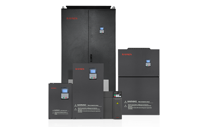
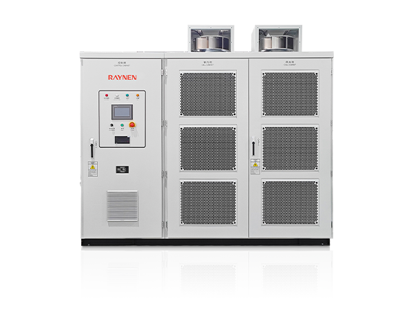
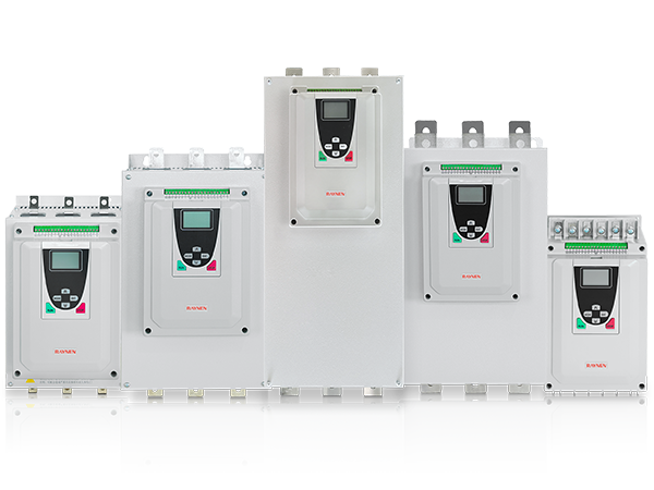
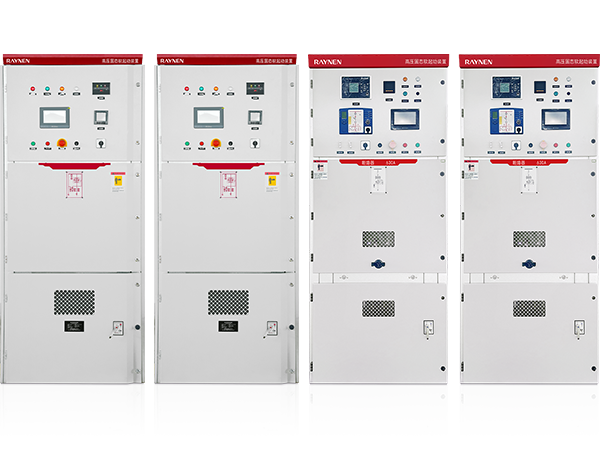





1.Introduction to AC Drives (Variable Frequency Drives) In the realm of modern industrial control an......
READ MOREHome / News / Industry News / A Practical Guide to Servo Drive: Uses, Selection, and Key Considerations
A Practical Guide to Servo Drive: Uses, Selection, and Key Considerations
Spend a shift on a production floor and you start to recognise servo systems by behaviour rather than by name. An axis stops exactly where it should, holds its position against a load, and repeats the same move all day without drifting. The device that makes this possible, usually tucked into a cabinet and wired to the motor's encoder, is the servo drive.
What follows is a practical walkthrough: what a servo drive is, how the closed loop actually closes, the types you will meet on different machines, and the details that decide whether a drive and motor pair behave well on your equipment.
Content
What a servo drive does, in plain terms
A servo drive is an electronic power amplifier with a control brain attached. It takes a low-power command from a motion controller, PLC or CNC, converts that into the three-phase current a motor needs, and then checks many times per second whether the motor is doing what it was told.
Three quantities matter, and the drive can regulate any one of them at a given moment:
- Torque — how hard the motor pushes, which is what tensioning, winding and pressing applications really care about.
- Velocity — how fast it turns, used for conveying, spindle work and coordinated feed rates.
- Position — where it stops, the foundation of every indexing, cut-off and pick-and-place move.
The distinction between a servo drive and a variable frequency drive is mostly about intent. A VFD is built to run pumps, fans and compressors at a steady speed while saving energy, usually with no feedback device at all. A servo drive is built for fast, frequent direction changes and accurate stopping, and it expects an encoder to report where the shaft actually is.
Inside the loop: command, feedback and correction
Following the command
The controller issues a setpoint in one of several forms: pulse and direction signals, a ±10 V analog reference, or a digital fieldbus telegram such as EtherCAT, CANopen or PROFINET. On a modern machine the fieldbus route is increasingly common because it carries position, velocity, torque and diagnostic data down a single cable.
Reading the feedback
An incremental encoder, an absolute encoder or a resolver reports shaft angle back to the drive. Resolution matters more than marketing numbers suggest — a finer encoder lets the drive hold position with less hunting, and absolute feedback removes homing routines after power-up. For brushless motors, the same signal also supplies the commutation information the power stage needs to switch at the right moment.
Correcting the error
Inside the drive, loops are nested. The current loop sits innermost and reacts fastest, the velocity loop wraps around it, and the position loop closes the outermost circle. Gains determine how aggressively the drive chases the error. Too soft and the axis lags; too stiff and it buzzes or oscillates. Practical commissioning is therefore a compromise between dynamic response and mechanical stiffness, usually reached through auto-tuning followed by manual trimming, with notch filters added to suppress resonance in the frame or belt.
Servo drive versus VFD versus stepper drive
These three controllers are often confused because they all sit between a controller and a motor. The table below sets out the practical differences.
| Characteristic | Servo drive | VFD | Stepper drive |
|---|---|---|---|
| Primary control target | Position, velocity or torque | Speed and torque | Position steps |
| Feedback device | Encoder or resolver | Usually none | None (open loop) |
| Torque at low speed | High, with short overload | Moderate | Falls away as speed rises |
| Behaviour at a stall | Holds position under load | Not intended for holding | Can lose steps silently |
| Typical application | CNC, robotics, packaging | Pumps, fans, compressors | Simple, low-cost indexing |
Types of servo drive you will encounter
Single-axis and dual-axis
A single-axis drive serves one motor. A dual-axis unit houses two power stages in one housing and shares a DC bus between them, which saves cabinet space and allows energy from a decelerating axis to be used by the other. On gantry and small multi-axis machines, this is a tidy arrangement.
Standalone, compact and integrated
Standalone drives mount on a panel and are wired to a separate motor. Compact models trim the footprint for small machines. Integrated designs merge the drive into the motor housing or behind the connector, which shortens cabling but limits heat dissipation and service access.
Interfaces and networks
Analog drives suit legacy retrofits and simple speed-following tasks. Pulse-train drives remain common on economical positioning axes. Fieldbus drives dominate wherever several axes must be coordinated within one controller cycle. Many machines need a mix, so a drive family that covers all three keeps the panel consistent.
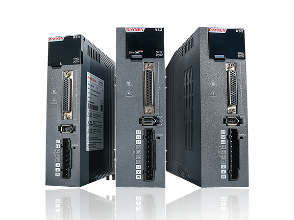
A standard-duty model is often the right starting point for general positioning work, especially when several axes share the same supply and cabinet.
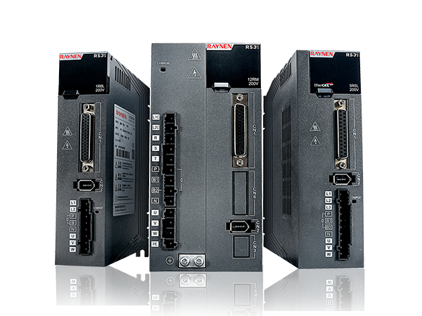
 RS3 Standard Servo Drive for General PositioningA standard-duty servo drive for general positioning, with configurable power, supply, flange and encoder options to specify shared-axis setups before ordering.View Product →
Sizing and selecting a servo drive
Most commissioning headaches trace back to specification rather than to the hardware itself. Working through the following list before ordering saves considerable time later:
- Load inertia — the reflected inertia ratio to the motor guides gain limits and stability.
- Continuous and peak torque — size for the continuous demand and confirm the peak covers acceleration.
- Speed range — check the constant-torque and constant-power regions, not just the rated rpm.
- Encoder type — match the drive's feedback interface to the motor you intend to use.
- Supply and inrush — confirm voltage, phase and any shared DC bus arrangement.
- I/O and safety — count the digital inputs and outputs needed, and confirm whether safe torque off is required.
- Environment — ambient temperature, mounting orientation and enclosure rating all affect derating.
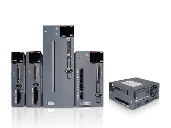
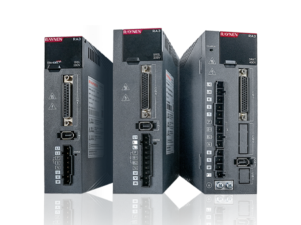
Where an axis needs more than basic positioning — electronic cam profiles, high-speed registration, or tight speed regulation under changing load — a full-function drive gives the extra headroom and tuning options.
 RA3 Fully Functional Servo DriveA full-function servo drive for demanding motion profiles, offered in multiple model variants with selectable power, supply, flange and encoder configurations.View Product →
Where servo drives earn their keep
The common thread across applications is a move that must repeat accurately, often at speed, often under a changing load. Typical examples include:
- CNC machine tools, where interpolation quality depends on how tightly each axis tracks its command.
- Packaging machinery, with flying cutters, film tensioning and registration control.
- Machine tools and cutting equipment, where feed rates must stay smooth through varying material resistance.
- Material handling and gantries, where two axes must stay synchronised or the load skews.
- Textile, printing and winding lines, where tension and speed are linked and drift shows up as waste.
- Lifting and positioning equipment, where holding torque and controlled braking matter for safety.
In each case the drive does not work alone. Its behaviour depends on the motor, the mechanics and the controller cycle time, which is why system-level thinking during selection beats comparing datasheets in isolation.
Matching drive to motor, and to real support
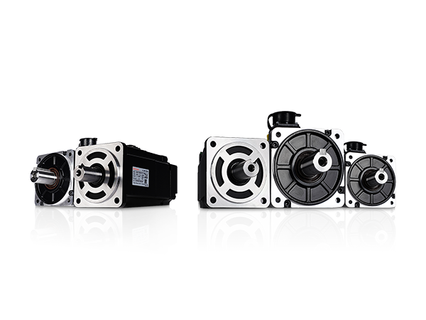
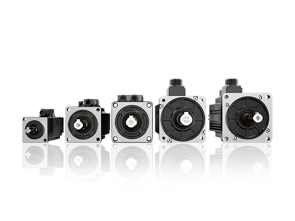
Drives and motors are tuned as a pair. Feedback resolution, rotor inertia, rated current and overload curve all interact, so the safest route is to select a drive and motor from one family where the parameters are already known to work together. A high-performance motor paired with a suitable drive gives a predictable starting point for tuning, and leaves room to refine stiffness once the machine is assembled.
 MA3 High-Performance Servo Motor SeriesA high-performance motor series with low- and high-inertia variants, selectable power, flange and encoder options for matched drive-and-motor tuning.View Product →
The other half of a good selection is documentation. Wiring diagrams, parameter lists and commissioning notes are what turn a delivery into a working axis, and having the right manual on hand shortens the fault-finding conversation considerably. Our user manual library collects the current editions for our drive and motor families, and the technical support team can help with sizing questions or parameter setup when a machine behaves unexpectedly.
A servo drive is a small part of the capital cost of a machine and a large part of how that machine feels to operate. Get the loop closure, the sizing and the drive-motor pairing right, and the axis simply does what it is told, shift after shift. Get them wrong, and every operator learns the sound of an unstable gain. Taking the specification step seriously is usually the difference between the two.
Previous Post
No previous article
Next Post
Programmable Logic Controller Explained: How PLCs Work and How to Choose

Copyright 2024 Fujian Raynen Technology Co.,Ltd. All Rights Reserved.
Privacy Policy  Motor Control Manufacturers