English
 Español
 عربى
عربى


1.Introduction to AC Drives (Variable Frequency Drives) In the realm of modern industrial control an......
READ MOREHome / News / Industry News / Industrial Servo Motor Explained: Types, Selection, and How to Get the Most Out of Them
Industrial Servo Motor Explained: Types, Selection, and How to Get the Most Out of Them
Content
- 1 How an Industrial Servo Motor Actually Works
- 2 Types of Industrial Servo Motors: AC, DC, and Brushless
- 3 Key Specifications to Evaluate When Selecting an Industrial Servo Motor
- 4 Industrial Servo Motor Drives: The System Is the Motor
- 5
- 6 Encoder Types Used with Industrial Servo Motors
- 7 Sizing an Industrial Servo Motor: A Practical Workflow
- 8 PID Tuning for Industrial Servo Motor Systems
- 9 Industrial Servo Motor Applications by Industry
- 10 Maintenance and Troubleshooting for Industrial Servo Motors
- 11 Industrial Servo Motor vs. Stepper Motor: Choosing Between Them
How an Industrial Servo Motor Actually Works
An industrial servo motor is a closed-loop motion control actuator — meaning it doesn't just spin and hope for the best. It continuously monitors its own position, speed, and torque through a feedback device (most commonly an encoder or resolver), compares the actual output against the commanded target, and corrects any deviation in real time. This self-correcting loop is what separates a servo system from a standard induction motor running open-loop at a fixed speed.
The core loop works like this: a motion controller sends a position or velocity command to a servo drive. The drive converts that command into electrical power delivered to the motor. The motor moves, and the encoder attached to the motor shaft sends back position data — typically millions of pulses per revolution on modern industrial encoders. The drive compares incoming encoder data against the commanded position, calculates an error signal, and adjusts the power output to eliminate that error. This happens thousands of times per second. The result is positioning accuracy within ±0.01 degrees and response times in the range of 1 to 3 milliseconds in typical industrial applications.
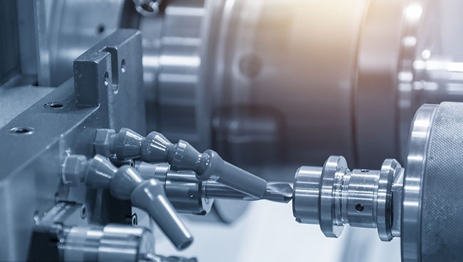
The practical consequence of this architecture is that an industrial servo motor drive system maintains commanded position even under changing load conditions. If a machining spindle encounters resistance mid-cut, the system compensates automatically rather than losing steps or slowing unpredictably — which is exactly what happens with open-loop alternatives like stepper motors under overload.
Types of Industrial Servo Motors: AC, DC, and Brushless
Industrial servo motors fall into three main technology categories. Understanding the differences helps you match the right motor type to your application requirements before getting into detailed specifications.
AC Servo Motors
AC servo motors are the dominant type in modern industrial automation. They use alternating current and are almost universally brushless, which means no brush maintenance, longer service life, and lower electrical noise. AC servo motors are available in both synchronous and asynchronous designs. Synchronous AC servo motors — using permanent magnets in the rotor — are the standard for precision motion control in CNC machines, packaging lines, and robotic axes. The rotor locks in step with the stator's rotating magnetic field, delivering extremely low vibration, high torque density, and exceptional positional accuracy. Asynchronous AC servo motors (induction type) are less precise but more rugged, tolerant of harsh environments, and suited for applications like conveyors, pumps, and variable-speed drives where absolute positioning is not required.
DC Servo Motors
DC servo motors — specifically brushed DC designs — were the industry standard before AC technology matured. They offer very fast response, excellent low-speed torque, and straightforward control, but the carbon brushes require periodic replacement, limit maximum speeds, and generate electrical noise that can interfere with sensitive electronics nearby. Brushed DC servo motors remain in use in retrofit situations, certain laboratory equipment, and applications where cost-effectiveness matters more than maintenance-free operation. Modern industrial installations rarely specify new brushed DC servo motors unless there's a compelling legacy reason.
Brushless DC (BLDC) Servo Motors
Brushless DC servo motors combine the speed and torque characteristics of DC motors with the maintenance-free operation of AC brushless designs. They use permanent magnet rotors with electronic commutation — hall effect sensors or encoders replace the mechanical brush-commutator system. BLDC servo motors deliver high efficiency, high torque-to-weight ratio, and long service life, which makes them the preferred choice in robotics, aerospace applications, surgical equipment, and compact automation systems where space and weight are constrained. For industrial factory automation, BLDC and synchronous AC servo motors are largely equivalent in performance terms — the distinction between them at the application level has narrowed considerably.
Quick Comparison of Industrial Servo Motor Types
| Type | Brushes | Torque Density | Precision | Maintenance | Typical Application |
|---|---|---|---|---|---|
| Synchronous AC | No | High | Very High | Low | CNC, robotics, packaging |
| Asynchronous AC | No | Medium | Medium | Low | Conveyors, pumps, fans |
| Brushed DC | Yes | Medium–High | High | High (brush replacement) | Legacy systems, lab equipment |
| Brushless DC (BLDC) | No | Very High | High | Very Low | Robotics, aerospace, compact automation |
Key Specifications to Evaluate When Selecting an Industrial Servo Motor
Servo motor datasheets contain a lot of numbers, and it's easy to focus on the wrong ones. These are the specifications that actually determine whether a motor will perform reliably in your application.
Continuous and Peak Torque
Continuous torque is the torque the motor can sustain indefinitely without overheating — the number that governs long-term thermal performance. Peak torque is typically two to three times continuous torque and represents what the motor can deliver during short acceleration bursts. For any application with cyclic motion, you need to calculate the root mean square (RMS) torque demand across the entire motion profile and ensure it stays below the continuous torque rating. Running an industrial servo motor continuously at or near peak torque will overheat it and shorten its winding insulation life. As a practical rule, size for at least 20–30% torque margin above your calculated RMS demand.
Speed Range
Industrial servo motors are characterized by two speed zones: the constant torque region below base speed, where full torque is available, and the field-weakening region above base speed, where available torque decreases as speed increases. If your application requires high torque at high speed simultaneously, verify that the motor's continuous power curve — not just its peak speed rating — covers your required operating point. Maximum speeds for industrial servo motors commonly range from 2,000 RPM to 6,000 RPM, with some compact high-speed designs reaching 8,000 RPM or more.
Inertia and Inertia Matching
Inertia matching is one of the most important and most frequently overlooked factors in servo motor selection. The inertia ratio — reflected load inertia divided by motor rotor inertia — determines how well the servo loop can control the load. An ideal inertia ratio for high-performance applications is between 1:1 and 3:1. Up to 10:1 is acceptable for less demanding applications. Beyond 10:1, the load dominates system dynamics, making the servo loop difficult to tune and producing sluggish, oscillating, or unstable behavior regardless of how capable the drive is. If your inertia ratio is too high, a planetary gearbox is often the solution — a 5:1 gearbox reduces reflected load inertia by a factor of 25 (by the square of the gear ratio), which can transform a poorly matched axis into a well-behaved one.
IP Rating and Environmental Protection
Industrial servo motors are available in protection ratings from IP54 (splash-resistant) up to IP67 or IP69K (fully sealed against dust and high-pressure water jets). For food processing, pharmaceutical manufacturing, washdown environments, or outdoor installations, the IP rating is a non-negotiable specification — not a secondary consideration. Most standard industrial servo motors carry IP65 as their default rating. Check the shaft seal specifically, as some motors use a lower-rated shaft seal even when the body is fully sealed.
Feedback Device Resolution
Encoder resolution determines how finely the servo loop can measure and correct position. Modern industrial servo motors typically use encoders with resolutions between 17-bit (131,072 counts per revolution) and 24-bit (16.7 million counts per revolution). A higher resolution encoder improves low-speed smoothness, reduces velocity ripple, and enables tighter position loops — but only if the drive can process the feedback rate and the mechanical system is precise enough to benefit. For most standard CNC and automation applications, a 20-bit to 23-bit absolute encoder is adequate. For ultra-precision applications — semiconductor equipment, metrology systems, optical positioning — higher resolution and a high-accuracy encoder are justified.
Industrial Servo Motor Drives: The System Is the Motor
A servo motor cannot be evaluated in isolation from its drive. The motor and drive together form the servo system, and specifying them separately without verifying compatibility leads to integration problems that are expensive to fix after commissioning. Every major industrial servo motor manufacturer — Yaskawa, Fanuc, Siemens, Mitsubishi, Allen-Bradley (Rockwell), Panasonic, and others — produces matched motor-drive families with known compatibility and optimized auto-tuning algorithms. Using a drive from one manufacturer with a motor from another is technically possible but requires careful attention to feedback protocol compatibility, current loop bandwidth, and inertia matching data.
Key drive features to evaluate alongside the motor specification include:
- Control modes: Position, velocity, and torque control modes serve different applications. CNC axes use position mode; spindle drives often use velocity or torque mode. Confirm the drive supports the mode required by your motion controller.
- Communication interface: Modern industrial servo drives communicate over EtherCAT, PROFINET, EtherNet/IP, MECHATROLINK, or CANopen, depending on the automation platform. Verify fieldbus compatibility with your PLC or motion controller before selecting a drive family.
- Safe Torque Off (STO): STO is a safety function (IEC 61800-5-2) that removes power from the motor in a safety event without requiring a full contactor between the drive and the motor. Most current industrial servo drives include STO as standard. Confirm this if your machine requires a safety category 3 or higher emergency stop circuit.
- Auto-tuning capability: Quality industrial servo drives include automated tuning routines that characterize the mechanical load and set initial PID gains. This doesn't eliminate the need for manual fine-tuning in demanding applications, but it significantly shortens commissioning time.
Encoder Types Used with Industrial Servo Motors
The encoder is the sensory system of the servo loop. Choosing the wrong encoder type for the environment or application is one of the most common causes of servo system problems in the field.
Incremental vs. Absolute Encoders
Incremental encoders output a stream of pulses as the shaft rotates — the controller counts these pulses to calculate position and velocity. The critical limitation is that position data is lost on power failure, requiring a homing sequence every time the machine starts up. For applications where homing is impractical — vertical axes that could fall during homing, machines in continuous 24/7 operation, or axes where the home position is not easily accessible — incremental encoders are a poor fit.
Absolute encoders provide a unique digital code for every shaft position, retaining this information even after a power cycle. No homing is required on startup. Single-turn absolute encoders track position within one revolution; multi-turn absolute encoders (using either geared counting mechanisms or battery-backed memory) track total revolutions in addition. For industrial applications involving vertical axes, gantries, or machines where startup time and positioning safety are critical, absolute encoders are strongly preferred despite their higher cost.
Optical vs. Magnetic Encoders
Optical encoders use a light source and a code disk with precisely etched patterns to generate position signals. They achieve very high resolutions — up to 24-bit or beyond — and excellent accuracy, but the optical disk is vulnerable to contamination by oil, coolant, and fine particles. Optical encoders are appropriate for clean environments such as semiconductor manufacturing, precision assembly, and medical equipment. In industrial machining, metalworking, or outdoor applications, they require protective measures or are replaced by magnetic alternatives.
Magnetic encoders use magnetized pole patterns on a target wheel and a sensor that detects the magnetic field variation as the shaft rotates. They offer lower resolution than optical designs but are highly resistant to contamination, moisture, shock, and vibration — the conditions common in heavy industrial environments. Modern magnetic encoders with 17-bit to 19-bit resolution are adequate for most industrial motion control applications where the environment rules out optical technology.
Sizing an Industrial Servo Motor: A Practical Workflow
Undersizing a servo motor causes stall faults, thermal shutdowns, and production interruptions. Oversizing wastes capital, increases inertia mismatch, and can make the control loop harder to tune. A systematic sizing workflow avoids both problems.
- Step 1 — Define the motion profile: Establish the full motion cycle: the distance traveled per cycle, the acceleration and deceleration times, the constant velocity periods, and the dwell time. Express this as a trapezoidal or S-curve velocity profile. This profile is the foundation for all torque and speed calculations.
- Step 2 — Calculate load inertia: Sum the reflected inertia of every rotating and translating component at the motor shaft — the mechanical load, coupling, gearbox, ballscrew or belt, and any attached tooling. This is the total load inertia the motor must accelerate and decelerate on every cycle.
- Step 3 — Calculate required torques: Determine acceleration torque (J_total × angular acceleration), friction torque (measured or estimated from the drivetrain), and gravity torque (for non-horizontal axes). Sum these for peak torque during acceleration. Calculate RMS torque over the full cycle for thermal sizing.
- Step 4 — Check inertia ratio: Divide total load inertia by the candidate motor's rotor inertia. Target 3:1 or below for high-performance applications; accept up to 10:1 for moderate dynamics. If the ratio exceeds 10:1, add a gearbox, select a higher-inertia motor, or reduce load inertia at the source.
- Step 5 — Verify the speed requirement: Confirm the required motor speed (accounting for any gear ratio) falls within the motor's continuous torque region. If high speed and high torque are required simultaneously, check the motor's continuous power curve at that operating point.
- Step 6 — Apply safety margins: Select the final motor with at least 20–30% margin on both peak torque and RMS torque. Real-world loads often exceed theoretical calculations due to friction variation, tooling changes, and dynamic load disturbances.
PID Tuning for Industrial Servo Motor Systems
Even a correctly sized servo motor with a properly matched drive will perform poorly if the control loop is not tuned. PID (Proportional-Integral-Derivative) tuning adjusts the three control gains that determine how aggressively the drive responds to position error, how it eliminates steady-state offset, and how it damps oscillation.
What Each Gain Does
Proportional (Kp) gain determines the immediate response to position error — higher Kp means faster, more aggressive correction. Too high and the system oscillates; too low and it responds sluggishly, with large position errors under load. Start by increasing Kp until the first signs of oscillation appear, then reduce by approximately 20%.
Derivative (Kd) gain dampens oscillation by responding to the rate of change of error, not the error magnitude. Adding Kd after setting Kp allows a higher proportional gain without instability. Think of it as the control system's shock absorber. Too much Kd amplifies noise and causes high-frequency chatter.
Integral (Ki) gain accumulates error over time and eliminates the steady-state position offset that proportional control alone cannot fully correct. Add Ki last and in small increments — too much integral gain causes slow, low-frequency oscillation called "integral windup."
Practical Tuning Guidance
Most modern industrial servo drives include auto-tuning functions that set initial gains based on measured mechanical response. Use auto-tune as a starting point, not a finished result. After auto-tuning, verify performance with the actual production motion profile — rapid cycles with full load — not just a slow test move. If the mechanical system has compliance (a belt drive, long flexible coupling, or multi-stage gearbox), notch filters at the resonant frequency of the mechanical system may be needed to suppress oscillation that PID tuning alone cannot eliminate. Bode plot analysis available in advanced servo drive software packages is the most efficient way to identify and suppress mechanical resonances.
Industrial Servo Motor Applications by Industry
Industrial servo motors are used wherever motion needs to be precise, repeatable, and fast. The following table summarizes the most common industrial applications, the primary performance demands in each, and the typical motor type used.
| Industry | Typical Application | Primary Requirement | Common Motor Type |
|---|---|---|---|
| CNC Machining | Axis drives, spindles | High positioning accuracy, rigid speed control | Synchronous AC servo |
| Robotics | Joint actuators, end effectors | High torque density, low inertia, compact size | BLDC servo, synchronous AC servo |
| Packaging | Pick-and-place, form-fill-seal, labeling | Fast cycle times, repeatable positioning | Synchronous AC servo |
| Semiconductor / Electronics | Wafer handling, PCB assembly | Ultra-high precision, clean room compatibility | Linear servo, high-resolution AC servo |
| Printing / Converting | Web tension control, register control | Smooth velocity control, fast disturbance rejection | Synchronous AC servo |
| Medical Equipment | Surgical robots, imaging systems | Quiet operation, precise torque control, compact | BLDC servo |
| Metal Forming | Press drives, bending machines | High peak torque, position accuracy at low speed | Synchronous AC servo (high-torque frame) |
Maintenance and Troubleshooting for Industrial Servo Motors
Industrial servo motors are designed for long service life — typically well over 20,000 hours in properly applied and maintained systems. Most field failures result from a small number of identifiable causes, and most of those are preventable with routine maintenance.
The Most Common Failure Modes
- Overheating: The leading cause of winding insulation degradation and premature motor failure. Caused by undersizing, blocked cooling vents, excessive ambient temperature, or repeated duty cycle violations. Infrared thermal imaging during normal operation is the fastest way to identify motors running hotter than expected before failure occurs.
- Encoder failure: Contamination (dust, oil, coolant) on optical code disks causes signal errors; mechanical shock damages encoder bearings; cable degradation from repeated flexing or EMI causes intermittent feedback errors. Symptoms include erratic motion, following errors, and position drift. Check cable shielding grounding first — poor EMI shielding is the most common cause of encoder signal problems in industrial environments.
- Bearing wear: Manifests as vibration, noise, and increased current draw. Caused by high radial or axial loads exceeding the motor's shaft load ratings, misalignment, or contamination ingress through a failed shaft seal. Replace bearings at manufacturer-recommended intervals or when vibration trending shows increasing levels.
- Positioning errors: If a servo axis starts missing commanded positions or triggering following error faults, the cause is usually encoder calibration drift, feedback cable issues, or PID gain degradation from changed mechanical conditions (worn gearbox, loose coupling). Recalibrate the encoder, inspect the feedback wiring, and re-run the drive's auto-tune function.
- Electrical faults: Insulation breakdown from moisture ingress, voltage spikes on the bus, or ground loops between the drive and motor. Run periodic insulation resistance tests (Megger tests) on motor windings and verify that drive bus clamping voltage protection is within specification.
Routine Maintenance Checklist
- Clean cooling fins and ventilation openings monthly in dusty environments; quarterly in clean environments.
- Inspect motor shaft seal and encoder cable connectors for oil or moisture contamination every six months.
- Check coupling alignment and fastener torque after any mechanical work on the driven machine.
- Log current draw and motor temperature at regular intervals and trend over time — gradual changes indicate developing mechanical or electrical problems before they cause unplanned downtime.
- Verify battery voltage on battery-backed multi-turn absolute encoders annually and replace before the battery drops below the minimum threshold. A dead encoder battery results in loss of the absolute position reference and a homing fault on startup.
- Perform insulation resistance tests annually on motor windings to detect moisture ingress before it causes a winding failure.
Industrial Servo Motor vs. Stepper Motor: Choosing Between Them
For motion control applications in the low-to-medium torque range with limited budgets, stepper motors are a common alternative to industrial servo motors. Understanding where each technology is genuinely the better choice prevents both over-engineering and under-specifying.
Stepper motors operate open-loop — they move in fixed incremental steps without position feedback. They're simpler, cheaper, and don't require drive tuning. They're appropriate for light loads, low speeds, and applications where missing a step occasionally is acceptable or load conditions are predictable and consistent. The limitations appear at higher speeds (torque drops off sharply above a few hundred RPM), under variable or shock loads (steps can be missed without any fault indication), and in high-duty cycle applications (thermal management becomes difficult without feedback).
Industrial servo motor systems are the right choice when:
- Positioning accuracy under varying loads is mandatory — a servo corrects for disturbances; a stepper cannot.
- The application requires operation at higher speeds with full torque — servo motors maintain rated torque across a wide speed range.
- The motion profile involves rapid acceleration and deceleration cycles — servos handle this more efficiently due to regenerative braking capability in modern drives.
- A missed position would cause a quality defect, a machine crash, or a safety event — the servo system will fault and alarm; the stepper will silently lose position.
- The duty cycle is high and continuous — servo motors with proper sizing run cooler and more efficiently than steppers at equivalent output power.
Previous Post
Low-Voltage Variable Frequency Drive: Everything You Need to Know Before You Buy or Install One
Next Post
Human Machine Interface Explained: What It Is and How to Get It Right
Copyright 2024 Fujian Raynen Technology Co.,Ltd. All Rights Reserved.
Privacy Policy  Motor Control Manufacturers