English
 Español
 عربى
عربى


1.Introduction to AC Drives (Variable Frequency Drives) In the realm of modern industrial control an......
READ MOREHome / News / Industry News / Programmable Logic Controller: Complete Guide to How PLCs Work, Types, Programming, and Selection
Programmable Logic Controller: Complete Guide to How PLCs Work, Types, Programming, and Selection
Content
- 1 What a Programmable Logic Controller Is and Why Industry Relies on It
- 2 How a PLC Works: The Scan Cycle Explained
- 3 PLC Hardware Components and Their Functions
- 4 Types of PLCs: Compact, Modular, and Rack-Based Systems
- 5 PLC Programming Languages Under IEC 61131-3
- 6 Industrial Communication Protocols Supported by Modern PLCs
- 7 Major PLC Manufacturers and Their Ecosystems
- 8 PLC vs DCS vs SCADA: Understanding the Differences
- 9 Key Factors to Evaluate When Selecting a PLC for a New Application
- 10 PLC Maintenance, Troubleshooting, and Lifecycle Management
What a Programmable Logic Controller Is and Why Industry Relies on It
A programmable logic controller (PLC) is a ruggedised industrial computer designed specifically to monitor inputs from sensors and field devices, execute a stored control program, and control outputs — such as motors, valves, actuators, and indicators — in real time. Unlike a general-purpose computer, a PLC is engineered to operate reliably in harsh industrial environments characterised by electrical noise, vibration, extreme temperatures, and dust, while executing control programs with deterministic timing — meaning the controller completes its scan cycle in a predictable, repeatable time regardless of process conditions. This combination of industrial hardening and real-time determinism is what makes PLCs the standard automation controller across manufacturing, process industries, utilities, building automation, and infrastructure worldwide.
The PLC was developed in the late 1960s specifically to replace the large banks of electromechanical relays that controlled automotive assembly lines — systems that were expensive to install, required significant rewiring to change, and demanded constant maintenance as relay contacts wore and failed. By replacing physical relay logic with a programmable software-based equivalent, the PLC allowed production engineers to modify machine behaviour by changing a program rather than rewiring a panel, dramatically reducing the time and cost of production changeovers. Sixty years later, the core concept remains unchanged, but modern programmable logic controllers have expanded from simple relay replacements into sophisticated automation platforms supporting high-speed motion control, process control, safety functions, machine vision integration, and industrial network communication across complex multi-system architectures.
How a PLC Works: The Scan Cycle Explained
The fundamental operating principle of a programmable logic controller is the scan cycle — a repeating sequence of operations that the PLC executes continuously as long as it is in run mode. Understanding the scan cycle is essential for understanding how a PLC behaves, particularly in time-critical applications where the response time to an input change determines whether the control system functions correctly.
A standard PLC scan cycle consists of four sequential stages. First, the input scan reads the current state of all connected digital and analogue inputs — sensors, switches, encoders, transmitters — and copies these values into an input image register in memory. Second, the program scan executes the control program stored in memory, using the input image values (not live input readings) to evaluate logic conditions and determine the required state of outputs. Third, the output scan writes the output image values determined by the program to the physical output hardware, activating or deactivating the connected devices. Fourth, the housekeeping stage handles communications, self-diagnostics, and updating of internal timers and counters before the cycle repeats.
The time required to complete one scan cycle — the scan time — is typically 1 to 10 milliseconds for most standard applications, though it increases with program complexity and I/O point count. The scan cycle architecture means that changes in input state are not acted upon until the next scan cycle, which introduces a maximum one-scan-cycle latency into the control response. For most industrial automation applications this latency is entirely acceptable. For high-speed applications — servo motion control, high-frequency counting, or safety functions requiring sub-millisecond response — specialised interrupt routines, dedicated motion processors, or separate safety PLCs are used to bypass the standard scan cycle latency.
PLC Hardware Components and Their Functions
A PLC system consists of several distinct hardware components that together form the complete automation controller. Understanding the function of each component clarifies how a PLC system is specified, assembled, and maintained.
Central Processing Unit (CPU)
The CPU module is the brain of the PLC — it contains the processor that executes the control program, the memory that stores the program and data, and the communication interfaces that connect to programming tools and other automation systems. CPU capability is characterised by processing speed (scan time per 1,000 instructions of ladder logic), program memory capacity (typically kilobytes to megabytes depending on the class of PLC), data memory for storing variable values and process data, and the range of supported communication protocols. High-end CPU modules also contain real-time clocks, data logging capability, and built-in OPC UA or MQTT servers for direct connection to industrial IoT and cloud systems without additional hardware.
Input/Output (I/O) modules
I/O modules are the physical interface between the PLC and the field devices — sensors, switches, valves, motors, and instruments — that the control system monitors and commands. Digital input modules receive on/off signals from devices such as proximity sensors, pushbuttons, and limit switches, converting the field-level voltage (typically 24VDC or 120/240VAC) into a logic level signal the CPU can read. Digital output modules switch power to field devices such as solenoid valves, motor starters, and indicator lamps. Analogue input modules convert continuously variable signals — 4-20mA current loops, 0-10V voltage signals, thermocouple voltages, RTD resistance values — into digital values the CPU can process. Analogue output modules convert digital values from the CPU into proportional analogue signals for controlling variable-speed drives, proportional valves, and other continuously variable devices. Specialised I/O modules include high-speed counter inputs for encoder feedback, serial communication modules, and safety-rated I/O for functional safety applications.
Power supply
The PLC power supply module converts incoming mains power (typically 120VAC or 240VAC) or DC bus power to the regulated DC voltages required by the CPU and I/O modules. Power supply selection involves matching the output current capacity to the total current consumption of all modules in the rack or system, with a margin of at least 20 to 30% for reliability and to accommodate future expansion. Redundant power supply configurations — where two power supply modules run in parallel with automatic failover — are standard in high-availability systems where an unplanned shutdown from a power supply failure would be unacceptably costly.
Backplane and rack
In rack-mounted modular PLC systems, the backplane is the circuit board that mechanically supports and electrically connects the CPU, power supply, and I/O modules. The backplane carries the internal data bus, power distribution, and in some systems the real-time synchronisation signals required for coordinated multi-module operation. Rack size — specified by the number of module slots — determines how many I/O modules can be installed in a single rack, and for systems requiring more I/O than a single rack can accommodate, multiple racks are connected via expansion cables or remote I/O over an industrial network.
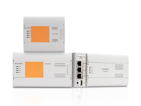
Types of PLCs: Compact, Modular, and Rack-Based Systems
PLCs are manufactured in several form factors suited to different scale and complexity requirements. Selecting the appropriate PLC form factor for an application involves matching the controller's I/O capacity, expandability, and processing capability to the current and projected future requirements of the machine or process being controlled.
| PLC type | Typical I/O count | Expandability | Best suited applications | Example products |
| Nano / micro PLC | 6 – 40 I/O | Limited or none | Simple machines, OEM equipment, relay replacement | Siemens LOGO!, Omron CP1E |
| Compact PLC | 20 – 256 I/O | Expansion modules available | Small to medium machines, packaging, HVAC | Allen-Bradley Micro820, Siemens S7-1200 |
| Modular PLC | 64 – 4,096 I/O | Highly expandable with remote I/O | Complex machines, production lines, process plant | Siemens S7-1500, Allen-Bradley ControlLogix |
| Rack-based PLC | 256 – 65,000+ I/O | Multiple racks, distributed I/O | Large process plants, power generation, DCS-equivalent control | Allen-Bradley PLC-5, GE RX3i, Schneider Premium |
| Safety PLC (SIL-rated) | Varies | Expandable with safety I/O | Emergency stop, safety interlock, SIL 1-3 functions | Pilz PSS 4000, Siemens S7-1500F, AB GuardLogix |
The compact PLC category has become the most significant growth area in the PLC market, driven by the Siemens S7-1200 and Allen-Bradley Micro820 class of products that offer capabilities previously associated only with full-size modular systems — including motion control, PID process control, and Ethernet-based industrial communication — in a small form factor suitable for panel mounting without a dedicated rack. For new machine automation projects with I/O counts below 200 points, a compact modular PLC is now the default starting point for most automation engineers rather than the larger rack-based systems that were necessary a decade ago.
PLC Programming Languages Under IEC 61131-3
PLC programming is standardised under IEC 61131-3, which defines five programming languages that compliant PLC development environments must support. Different languages suit different types of control logic and different engineering backgrounds, and most modern PLC programming tools allow multiple languages to be used within a single project — allowing engineers to choose the most appropriate language for each section of the program.
Ladder Diagram (LD)
Ladder Diagram is the most widely used PLC programming language, particularly in North America and in discrete manufacturing environments. The graphical representation mimics the relay logic diagrams that PLCs were originally designed to replace — horizontal rungs of logic connect left and right power rails, with normally open and normally closed contact symbols representing input conditions and coil symbols representing output commands. Ladder logic is intuitive for electrical engineers familiar with relay circuit diagrams and is easy to read and troubleshoot online (with the PLC in run mode, active elements are highlighted in the programming software, allowing fault conditions to be traced visually). The limitation of Ladder Diagram is that it becomes unwieldy for complex mathematical operations, data manipulation, and sequential programming that are more naturally expressed in text-based languages.
Function Block Diagram (FBD)
Function Block Diagram represents control logic as interconnected graphical blocks — each block encapsulates a specific function (AND gate, PID controller, counter, timer, motor function block) with input and output connections shown as wires between blocks. FBD is the dominant language in process control applications — it maps naturally to the piping and instrumentation diagram (P&ID) representation familiar to process engineers, and the encapsulation of complex functions (PID loops, valve control, motor protection) in standardised reusable function blocks reduces programming effort significantly in process plant applications. Most process and safety-oriented PLC platforms offer extensive libraries of IEC 61511-compliant function blocks for common process control and safety functions.
Structured Text (ST)
Structured Text is a high-level text-based language syntactically similar to Pascal or C, supporting conditional statements, loops, mathematical expressions, string handling, and complex data structures that are cumbersome or impossible in graphical languages. ST is increasingly used by automation engineers with software development backgrounds and is the preferred language for complex data processing, recipe management, communication handling, and any application requiring sophisticated algorithmic logic that graphical languages cannot express efficiently. The IEC 61131-3 standard's definition of Structured Text has made it genuinely portable between different PLC platforms — code written in ST for one brand's PLC can be adapted to another brand's platform with relatively minor modifications, unlike Ladder Diagram code which tends to use manufacturer-specific instructions and conventions.
Sequential Function Chart (SFC)
Sequential Function Chart represents control programs as a flowchart of steps and transitions — each step contains actions (programmed in LD, FBD, or ST), and each transition defines the condition that must be satisfied for the program to advance to the next step. SFC is the natural language for sequencing applications — washing machine cycles, batch process sequences, multi-stage assembly operations, and any application where a machine must perform a defined series of operations in order. Programming a complex sequential process in Ladder Diagram produces large, difficult-to-follow programs; the same sequence expressed in SFC is immediately readable as a process flow and is significantly easier to debug and modify.
Industrial Communication Protocols Supported by Modern PLCs
Modern programmable logic controllers are network devices as much as they are automation controllers. The communication capabilities of a PLC determine how it integrates with other automation equipment, supervisory systems, enterprise databases, and cloud platforms — a increasingly important consideration as industrial automation evolves toward connected Industry 4.0 architectures.
- EtherNet/IP: The dominant industrial Ethernet protocol in the Allen-Bradley / Rockwell Automation ecosystem, and widely supported by third-party I/O, drives, and instruments. EtherNet/IP uses standard TCP/IP and UDP infrastructure, allowing PLCs to share the same physical Ethernet network as office systems while maintaining deterministic industrial performance through traffic management. It is the protocol of choice for large North American manufacturing automation systems.
- PROFINET: The industrial Ethernet protocol developed and promoted by Siemens and the PROFIBUS and PROFINET International (PI) organisation. PROFINET is the standard communication backbone for Siemens S7 PLC systems and is widely supported across European industrial automation. PROFINET IRT (Isochronous Real Time) provides sub-millisecond cycle times for motion control applications requiring tight synchronisation between multiple axes.
- Modbus TCP/RTU: The oldest and most universally supported industrial communication protocol, available in virtually every PLC, instrument, and field device on the market. Modbus is simple, well-documented, and royalty-free, making it the default choice for integrating third-party instruments and legacy equipment into modern PLC systems. Its limitations — no native security features, limited diagnostic capability, and master-slave architecture that restricts multi-master configurations — have led to its displacement by EtherNet/IP and PROFINET in new automation systems, but its universal availability ensures it will remain in use for decades.
- OPC UA (Unified Architecture): The modern standard for platform-independent, secure data exchange between industrial automation systems and higher-level systems including SCADA, MES, ERP, and cloud platforms. OPC UA provides a standardised information model, built-in security (authentication, authorisation, and encryption), and the ability to represent complex data structures and relationships rather than just raw register values. The adoption of OPC UA as the communication interface for Industry 4.0 and IIoT architectures has made native OPC UA server capability in PLC CPUs a standard feature of high-end automation platforms.
- IO-Link: A point-to-point serial communication standard for connecting intelligent sensors and actuators to the PLC I/O system, providing bidirectional digital communication that allows parameter setting, diagnostics, and identification data to be exchanged between the field device and the PLC in addition to the primary process value. IO-Link is rapidly displacing conventional 4-20mA and digital I/O connections for new sensor and actuator installations because the additional diagnostic and parameterisation capability it provides reduces commissioning time and improves predictive maintenance capability significantly.
Major PLC Manufacturers and Their Ecosystems
The PLC market is dominated by a small number of large automation companies, each of which offers a complete ecosystem of PLC hardware, programming software, I/O modules, drives, HMI panels, and communication infrastructure that is designed to work together seamlessly. Choosing a PLC from a particular manufacturer typically means committing to that manufacturer's ecosystem for the full automation system, which has significant implications for integration, spare parts, training, and long-term support.
| Manufacturer | Key PLC families | Programming environment | Primary industrial network | Market strength |
| Siemens | S7-1200, S7-1500, S7-300/400 | TIA Portal (Step 7) | PROFINET, PROFIBUS | Europe, global process industries |
| Rockwell Automation (Allen-Bradley) | ControlLogix, CompactLogix, Micro820 | Studio 5000 Logix Designer | EtherNet/IP, DeviceNet | North America, automotive, food and beverage |
| Mitsubishi Electric | MELSEC iQ-R, iQ-F, Q Series | GX Works3 | CC-Link IE, SLMP | Asia-Pacific, automotive, semiconductor |
| Schneider Electric | Modicon M580, M340, TM Series | EcoStruxure Control Expert | Modbus TCP, EtherNet/IP | Process industries, energy, infrastructure |
| Omron | NX, NJ, CP Series | Sysmac Studio | EtherNet/IP, EtherCAT | Asia, machine automation, motion control |
PLC vs DCS vs SCADA: Understanding the Differences
PLCs are frequently discussed alongside Distributed Control Systems (DCS) and Supervisory Control and Data Acquisition (SCADA) systems, and the boundaries between these categories have blurred significantly as technology has evolved. Understanding the distinctions — and where they have converged — is important for specifying the correct automation architecture for a given application.
A Distributed Control System is an automation architecture in which control functions are distributed across multiple controllers deployed close to the process being controlled, all connected to a centralised supervisory system through a high-reliability plant network. DCS systems were developed for large continuous process applications — oil and gas, petrochemical, power generation, pharmaceutical manufacturing — where thousands of analogue control loops, complex interlock logic, and comprehensive alarm management are required across a large physical plant. DCS systems prioritise high availability (redundant controllers, I/O, power, and networks as standard), comprehensive process data historian capability, and integrated operator station displays. The distinction between a modern high-end modular PLC system and an entry-level DCS is now marginal in terms of functionality — the primary differences are in the software environment, the vendor's application focus, and the commercial model.
SCADA (Supervisory Control and Data Acquisition) refers specifically to the supervisory layer — the software system that collects data from PLCs and other field controllers, presents process information to operators through graphical HMI displays, logs historical data, and may send setpoint commands back to the controllers. SCADA is not a replacement for a PLC — it is the layer above the PLC that provides human oversight and data management. A typical industrial automation architecture combines PLCs at the machine or process control level, an industrial network carrying data between PLCs and supervisory systems, and a SCADA or MES system providing operator interface, historical data, and integration with business systems.
Key Factors to Evaluate When Selecting a PLC for a New Application
Selecting the right programmable logic controller for a new machine or process control application involves evaluating a range of technical and commercial factors that together determine whether the system will meet its functional requirements, be delivered on schedule, and be supportable throughout its operational life. The following framework covers the most important evaluation criteria.
- I/O count and type: Identify all inputs and outputs required — digital inputs, digital outputs, analogue inputs, analogue outputs, high-speed counter inputs, pulse train outputs for stepper motors — and add a 20 to 25% spare capacity margin for future modifications and additions. Ensure the I/O module range for the selected PLC family includes the specific types and voltage ranges needed for your field devices — not every PLC platform offers every I/O variant, and adapting non-standard field devices to a limited I/O range adds cost and complexity.
- Processing performance requirements: Determine whether the application requires standard relay-replacement logic (any modern PLC is adequate), PID process control (most compact and modular PLCs support this as standard), motion control (requires a PLC with integrated motion control capability or a separate motion controller), or safety functions (requires a SIL-rated safety PLC or safety function module). Match the CPU scan time specification to the fastest required control response in the application — for motion control or high-speed counting applications, standard scan times of 5 to 10ms may be insufficient.
- Communication requirements: Identify the protocols required to interface with all other equipment in the system — drives, HMI panels, instruments, vision systems, robots, and supervisory systems. Confirm that the PLC can act as the required master, slave, or peer in each communication relationship. If OPC UA connectivity to a SCADA or MES system is required, verify whether this is native in the CPU or requires an additional communication module.
- Environmental and installation requirements: Check the operating temperature range, IP (ingress protection) rating of the CPU and I/O modules, vibration and shock ratings, and any specific certifications required for the installation environment — ATEX or IECEx for explosive atmospheres, marine certifications for offshore or vessel installations, or specific industry certifications for food and beverage or pharmaceutical applications.
- Programming software and training availability: Evaluate the ease of use of the programming environment, the quality of the documentation, and the availability of training for the programming and maintenance teams who will work with the system. A powerful PLC platform that the engineering team cannot program efficiently will deliver poorer results than a more modestly specified system that the team knows well. If the project involves an unfamiliar platform, factor in realistic training and learning time in the project schedule.
- Long-term support and product lifecycle: Verify the manufacturer's stated product lifecycle for the specific PLC family — how many years of availability and spare parts support are committed. Some PLC families have been discontinued with limited transition paths, leaving installed systems orphaned on obsolete hardware. Prefer platforms from manufacturers with demonstrated commitment to long-term support and clear migration paths when eventual product changes are needed. Check whether the selected CPU and I/O modules are current production items or legacy products approaching end of life.
PLC Maintenance, Troubleshooting, and Lifecycle Management
A PLC system in continuous operation requires proactive maintenance and lifecycle management to maintain reliability and avoid unplanned downtime. The following practices are standard in well-run automation engineering operations.
- Program backup and version control: Maintain current, verified backups of all PLC programs and configuration files in a secure, version-controlled repository. A PLC that loses its program due to battery failure, CPU failure, or unintended overwrite can bring a production line to a complete halt until the program is restored. Test the restore procedure from backup at least annually to confirm the backup is complete and the restore process works correctly.
- Battery maintenance: Most PLC CPUs use a lithium battery to maintain program memory and real-time clock values during power outages. Battery life is typically three to five years, and most CPUs provide a low battery warning signal before failure. Replace batteries on a scheduled basis — annually in critical applications — rather than waiting for the low battery alarm, which leaves insufficient margin for unplanned extended outages.
- Firmware updates: PLC manufacturers regularly release firmware updates that address security vulnerabilities, fix bugs, and add features. Establish a process for evaluating and applying firmware updates — not every update should be applied immediately in production systems, but ignoring all updates creates security risks and may leave known bugs unaddressed. Test firmware updates on a non-production system before applying to production PLCs.
- Spare parts management: Maintain a spare parts inventory appropriate to the criticality of the controlled process. At minimum, hold one spare of each CPU module and the most commonly used I/O module types. For critical applications where the cost of downtime is very high, hold complete spare racks or systems in a ready-to-deploy state. The correct approach to spare parts is to determine the maximum acceptable downtime for the system and work backward to determine what spares inventory is needed to meet that target.
- Cybersecurity hardening: PLC systems connected to plant networks and beyond are increasingly targeted by cyber attacks — the Stuxnet incident demonstrated that even isolated industrial control systems can be compromised. Basic cybersecurity hygiene for PLC systems includes network segmentation (isolating the control network from the corporate IT network behind a demilitarised zone), disabling unused communication ports and services on the PLC CPU, implementing user access controls and password policies on programming software, and monitoring network traffic for anomalies using industrial intrusion detection systems.
Previous Post
Medium-Voltage Soft Starter Explained: How It Works, Where It's Used, and How to Choose One
Next Post
The Complete Guide to Industrial Servo Motors: How They Work and Why They Matter
Copyright 2024 Fujian Raynen Technology Co.,Ltd. All Rights Reserved.
Privacy Policy  Motor Control Manufacturers