English
 Español
 عربى
عربى
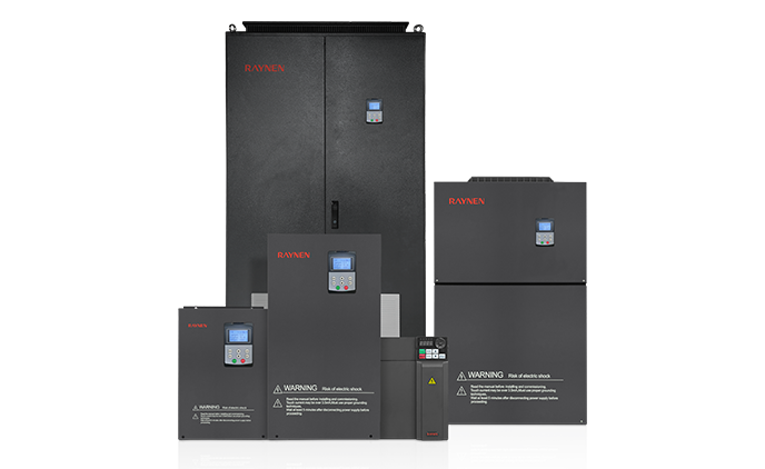


1.Introduction to AC Drives (Variable Frequency Drives) In the realm of modern industrial control an......
READ MOREHome / News / Industry News / AC Servo Drive Explained: How It Works, How to Choose One, and How to Get the Most Out of It
AC Servo Drive Explained: How It Works, How to Choose One, and How to Get the Most Out of It
Content
- 1 What Is an AC Servo Drive and How Does It Work?
- 2 AC Servo Drive vs. VFD vs. Stepper Driver: Key Differences
- 3 Core Components of an AC Servo Drive System
- 4 AC Servo Drive Control Modes Explained
- 5 Key Specifications When Selecting an AC Servo Drive
- 6 AC Servo Drive Applications Across Industries
- 7 How to Commission and Tune an AC Servo Drive
- 8 Common AC Servo Drive Faults and How to Diagnose Them
What Is an AC Servo Drive and How Does It Work?
An AC servo drive is an electronic power amplifier and control unit that regulates the operation of an AC servo motor by continuously monitoring the motor's actual position, speed, and torque and adjusting the electrical power delivered to it in real time to match a commanded reference signal. The word "servo" comes from the Latin "servus," meaning servant — and that is precisely what an AC servo drive does: it serves the command signal by making the motor follow it with extreme precision, correcting any deviation between the commanded and actual motor state within milliseconds. This closed-loop feedback architecture is what fundamentally distinguishes an AC servo drive system from an open-loop variable frequency drive (VFD) or a simple on/off motor controller.
The AC servo drive system consists of three tightly integrated components: the servo drive itself (sometimes called a servo amplifier or servo controller), the AC servo motor, and the feedback device — most commonly a rotary encoder or resolver mounted on the motor shaft. The encoder continuously reports the motor's exact angular position back to the drive, which compares this measured position against the position commanded by the machine controller (typically a PLC or motion controller) and calculates the precise voltage and current waveforms needed to eliminate any error between the two. This process happens thousands of times per second, enabling AC servo drives to achieve positioning accuracies measured in fractions of a degree, speed regulation within a fraction of a percent of setpoint, and torque response times measured in single-digit milliseconds.
AC Servo Drive vs. VFD vs. Stepper Driver: Key Differences
One of the most common sources of confusion in motion control is understanding how an AC servo drive differs from a variable frequency drive (VFD) and a stepper motor driver. All three control motor speed and position to varying degrees, but they differ fundamentally in their control architecture, performance capabilities, and appropriate applications. The table below clarifies the key distinctions:
| Feature | AC Servo Drive | Variable Frequency Drive | Stepper Driver |
| Control Type | Closed-loop (full feedback) | Open or closed-loop | Open-loop (typically) |
| Position Accuracy | Extremely high (encoder-based) | Low–Moderate | Moderate (step-based) |
| Speed Range | Very wide (1:5000+) | Moderate (1:100) | Limited (low speed torque drops) |
| Torque at Low Speed | Full rated torque at zero speed | Reduced at low speed | Good at low speed, drops at high |
| Response Speed | Milliseconds | Tens of milliseconds | Fast but no error correction |
| Typical Motor Power | 50W – 55kW | 0.2kW – Several MW | Under 2kW typically |
| Cost | Higher | Moderate | Lower |
| Best Application | Precision motion control | Pump, fan, conveyor speed | Light-duty positioning |
The fundamental advantage of an AC servo drive system over both VFDs and stepper drivers is its ability to detect and correct positioning errors in real time. If an external disturbance — a sudden load change, mechanical vibration, or momentary power fluctuation — causes the motor to deviate from its commanded position, the AC servo drive immediately applies corrective torque to bring it back. A stepper driver has no knowledge of whether the motor actually reached its commanded position; a missed step due to overload goes undetected and accumulates as positioning error until the machine is homed again.
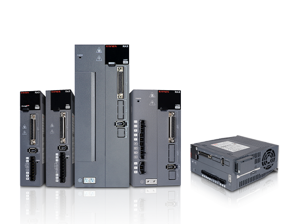
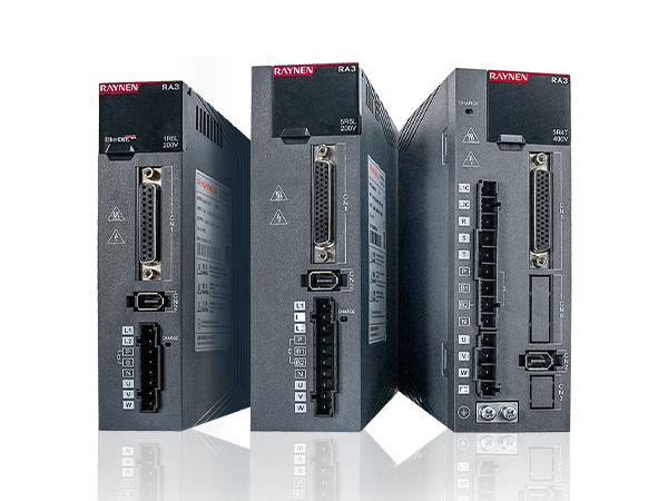
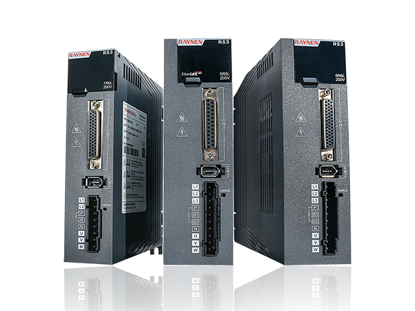
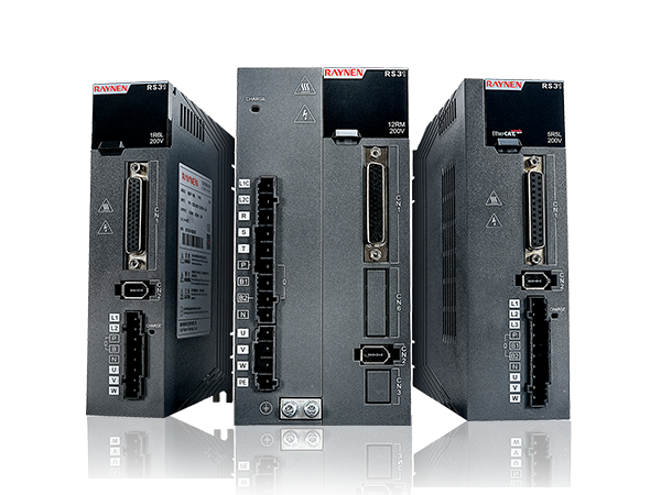
Core Components of an AC Servo Drive System
Understanding what is inside an AC servo drive and how each component contributes to overall system performance helps engineers make better design, tuning, and troubleshooting decisions. A complete AC servo drive system consists of the following integrated elements:
Power Stage and Rectifier
The power stage of an AC servo drive converts the incoming AC supply voltage (typically single-phase 200–240V for smaller drives, or three-phase 380–480V for larger units) into a controlled DC bus voltage through a rectifier and filter capacitor bank. This DC bus voltage is then chopped by an IGBT (Insulated Gate Bipolar Transistor) inverter stage using pulse-width modulation (PWM) at switching frequencies typically between 4 kHz and 16 kHz to generate the variable-frequency, variable-voltage three-phase AC output that drives the servo motor. The quality of the IGBT switching circuitry directly affects the drive's efficiency, heat generation, and the smoothness of the current waveforms delivered to the motor — factors that influence both motor performance and acoustic noise levels.
Digital Signal Processor (DSP) Control Board
The intelligence of the AC servo drive resides in its DSP-based control board, which executes the position, velocity, and current control loops at update rates typically ranging from 1 kHz for the position loop to 10–20 kHz for the current (torque) loop. The DSP reads the encoder feedback signal, computes the error between commanded and actual states at each loop update, applies the PID (Proportional-Integral-Derivative) control algorithm with feed-forward compensation, and outputs the PWM switching commands to the IGBT power stage. Modern AC servo drive DSPs also handle parameter storage, fault detection, protection functions, communication protocol processing, and auto-tuning algorithms that simplify initial commissioning.
Encoder Interface and Feedback Processing
The encoder interface circuit receives the position feedback signal from the servo motor's encoder or resolver and converts it into digital position data that the DSP can use for control calculations. Modern AC servo drives support a wide range of encoder types including incremental encoders (A/B/Z quadrature signals), absolute encoders (single-turn and multi-turn), serial encoders (Endat, BiSS, Hyperface), and resolvers — each with different resolution, noise immunity, and absolute position retention characteristics. Higher encoder resolution allows finer positioning and smoother low-speed operation. A 20-bit absolute encoder, for example, provides over one million counts per revolution, enabling positioning resolution of less than 0.001 degrees.
Communication and I/O Interface
AC servo drives communicate with machine controllers through a combination of digital I/O signals and fieldbus communication interfaces. Standard digital I/O typically includes servo enable, fault reset, homing input, limit switch inputs, and alarm output signals. Fieldbus options vary by manufacturer and application but commonly include EtherCAT, PROFINET, Modbus RTU/TCP, CANopen, DeviceNet, and MECHATROLINK-III. EtherCAT has become the dominant high-performance fieldbus for multi-axis servo systems due to its distributed clock synchronization capability, which enables multiple servo drives to synchronize their motion with nanosecond-level timing accuracy — essential for coordinated multi-axis CNC and robotics applications.

AC Servo Drive Control Modes Explained
AC servo drives operate in three fundamental control modes — position mode, velocity mode, and torque mode — each corresponding to a different layer of the servo drive's three-loop control hierarchy. Understanding which mode to use for a given application is one of the most important decisions in servo system design.
Position Control Mode
In position control mode, the AC servo drive accepts a position command — typically as a pulse train (step/direction or quadrature encoder following) or via a fieldbus position reference — and controls the motor to reach and hold the commanded position with minimal error. The drive runs all three control loops simultaneously: the outer position loop generates a velocity command, the middle velocity loop generates a torque command, and the inner current/torque loop controls the motor's electrical currents to produce the required torque. Position mode is used in the vast majority of machine tool, pick-and-place, packaging, and semiconductor manufacturing applications where moving to specific positions repeatedly and accurately is the primary requirement.
Velocity Control Mode
In velocity control mode, the drive accepts a speed reference (analog ±10V, digital preset speeds, or fieldbus velocity command) and regulates the motor's rotational speed to match it precisely regardless of load variations. The position loop is inactive in this mode, and the drive runs only the velocity and current loops. Velocity mode is used in applications like winding machines, printing presses, conveyor synchronization, and spindle drives where maintaining a precise, stable speed — rather than reaching a specific position — is the primary control objective. AC servo drives in velocity mode can maintain speed regulation within 0.01% of setpoint even under significant load fluctuations, a performance level that standard VFDs cannot match.
Torque Control Mode
In torque control mode, the drive regulates the motor's output torque (proportional to motor current) to match a commanded torque reference, allowing the motor's speed to be determined by the mechanical load. Only the innermost current control loop is active in this mode. Torque mode is used in tension control applications such as wire drawing, film winding, and cable laying, where maintaining a constant tension force — rather than a speed or position — is the objective. It is also used in force-controlled assembly applications and in master-slave multi-axis systems where the master drive controls position and the slave drives follow in torque mode to share the mechanical load.
Key Specifications When Selecting an AC Servo Drive
Selecting the correct AC servo drive for a specific application requires matching the drive's electrical and performance specifications to the requirements of both the servo motor and the machine. These are the most important parameters to evaluate:
- Continuous and Peak Current Rating: The drive's continuous current rating must meet or exceed the servo motor's rated current. The peak current rating determines the drive's ability to deliver short-duration overload current for acceleration — typically 200–300% of continuous rated current for 1–3 seconds in high-performance AC servo drives. Undersizing the drive's peak current capability results in slow acceleration and poor dynamic response.
- Input Voltage and Phase: Confirm that the drive's input voltage specification matches the available supply — single-phase 200–240V for drives up to approximately 750W–1.5kW, three-phase 200–240V or 380–480V for larger drives. Using a three-phase drive on a single-phase supply (a common workaround in low-power applications) requires derating the drive's current output to account for the unbalanced rectifier loading.
- Encoder Interface Compatibility: Verify that the drive's encoder input is compatible with the encoder type fitted to your servo motor. Using a drive with a different encoder protocol than the motor's encoder requires an external converter interface, adding cost and latency to the feedback path. Whenever possible, select a matched drive and motor from the same manufacturer's servo system to ensure full encoder compatibility and optimized tuning parameters.
- Communication Protocol: Select an AC servo drive that natively supports the fieldbus protocol used by your machine's PLC or motion controller. EtherCAT is the preferred choice for high-performance synchronized multi-axis systems. PROFINET suits Siemens-dominated automation environments. Modbus RTU is widely used in simpler single-axis applications where cycle time requirements are not demanding.
- Regenerative Braking Capability: When a servo motor decelerates a high-inertia load, it acts as a generator and returns energy to the DC bus. If this regenerated energy exceeds the drive's internal braking resistor capacity, the DC bus voltage rises and can trigger an overvoltage fault. For applications with frequent or rapid deceleration of high-inertia loads, select a drive with an external dynamic braking resistor option or active regenerative capability that feeds braking energy back into the supply grid.
- Safety Functions: Modern AC servo drives increasingly incorporate integrated functional safety features certified to IEC 61800-5-2, including Safe Torque Off (STO), Safe Stop 1 (SS1), Safe Limited Speed (SLS), and Safely Limited Position (SLP). These functions allow the drive to enter a safe state in response to a safety system command without requiring a separate contactor or full drive power removal, simplifying safety circuit design and reducing hardware costs in safety-critical machine applications.
AC Servo Drive Applications Across Industries
AC servo drives are found across virtually every sector of modern manufacturing and automation because the combination of precision, speed, and dynamic response they provide is either impossible or impractical to achieve with other motion control technologies. Here are the major application areas and how servo drives specifically benefit each one:
CNC Machine Tools
CNC machining centers, lathes, grinding machines, and EDM equipment rely on AC servo drives for their axis positioning and spindle control. In a five-axis machining center, five or more AC servo drives operate simultaneously under coordinated control from the CNC controller, each maintaining sub-micron positioning accuracy on its respective axis while responding to rapid trajectory changes at feed rates of several meters per minute. The stiffness of the servo position loop — its ability to resist position error under cutting forces — directly determines the machined part's dimensional accuracy and surface finish quality, making servo drive tuning a critical aspect of machine tool performance optimization.
Industrial Robotics
Every joint of an industrial robot arm is driven by a dedicated AC servo drive and motor, with the robot controller coordinating all axes simultaneously to execute smooth, accurate trajectories through three-dimensional space. Articulated robots used in welding, painting, assembly, and material handling applications typically incorporate six servo axes, while SCARA and delta robots use three to four axes. The servo drive's torque response bandwidth directly determines the robot's ability to maintain positional accuracy during rapid acceleration and deceleration of the arm segments, which is the primary determinant of cycle time and process repeatability in robotic manufacturing cells.
Packaging and Printing Machinery
High-speed packaging lines — form-fill-seal machines, cartoners, case packers, and labeling equipment — use AC servo drives to replace mechanical cam and gearbox systems that previously synchronized machine elements. Electronic gearing and camming functions built into modern AC servo drives allow machine designers to create virtual mechanical relationships between axes entirely in software, enabling rapid format changes through parameter adjustment rather than physical cam or gearbox replacement. Printing presses use AC servo drives for web tension control, register correction, and cutting cylinder phase adjustment, enabling print register accuracy of fractions of a millimeter at production speeds of hundreds of meters per minute.
Semiconductor and Electronics Manufacturing
Wafer handling robots, die bonding machines, wire bonders, PCB drilling equipment, and SMT pick-and-place machines represent some of the most demanding AC servo drive applications in existence. These machines require positioning accuracy measured in microns, settling times of a few milliseconds, and the ability to execute hundreds of thousands of precise positioning cycles per day without accumulating positioning error or experiencing mechanical wear-related accuracy degradation. Linear servo motors driven by high-bandwidth AC servo drives are increasingly used in these applications to eliminate the compliance and backlash of rotary-to-linear mechanical transmission elements.
How to Commission and Tune an AC Servo Drive
Proper commissioning and tuning of an AC servo drive is essential for achieving the positioning accuracy, dynamic response, and stability that the hardware is capable of delivering. A poorly tuned servo drive system — even one built from high-quality components — will exhibit overshoot, oscillation, slow response, or instability that degrades machine performance. The following steps represent the standard commissioning workflow for most AC servo drive systems:
- Motor Parameter Configuration: Enter the servo motor's rated parameters — voltage, current, speed, encoder type and resolution, pole count, and back-EMF constant — into the drive's parameter set. Most manufacturers provide pre-configured motor parameter files for their own motors that can be loaded directly, eliminating manual entry errors. For third-party motor combinations, these parameters must be entered manually from the motor's datasheet.
- Auto-Tuning: Modern AC servo drives include auto-tuning functions that identify the mechanical system's inertia ratio (the ratio of load inertia to motor inertia) and automatically calculate initial PID gains for all three control loops. Run the auto-tuning routine with the motor connected to the actual mechanical load — not uncoupled — to get meaningful inertia measurement results. The inertia ratio is the single most important parameter for initial gain calculation; a system with a high inertia ratio (load inertia much greater than motor inertia) requires lower gains to maintain stability.
- Manual Gain Refinement: Auto-tuning provides a starting point, but manual refinement is usually needed for optimal performance. Increase the velocity loop gain (proportional gain) until the system begins to exhibit slight oscillation, then reduce it by 20–30%. Adjust the velocity loop integral gain to eliminate steady-state velocity error without introducing low-frequency hunting. Finally, tune the position loop proportional gain to achieve the desired position settling behavior — faster settling requires higher gain, but excessive position loop gain causes overshoot or oscillation on position commands.
- Notch Filter Configuration: If mechanical resonance is causing high-frequency oscillation or acoustic noise at specific speeds, configure the drive's built-in notch filters to attenuate the resonant frequency. Most modern AC servo drives include two or more configurable notch filters and automatic vibration suppression functions that can identify and filter mechanical resonance frequencies without manual frequency analysis equipment.
- Protection Parameter Setting: Configure overcurrent, overvoltage, undervoltage, overspeed, encoder error, and motor overtemperature protection thresholds before putting the system into production. Set the following error limit — the maximum allowable deviation between commanded and actual position before the drive faults — to an appropriate value for the application: tight enough to detect real positioning problems, but loose enough to avoid nuisance faults during normal acceleration transients.
Common AC Servo Drive Faults and How to Diagnose Them
AC servo drives are sophisticated electronic systems that self-monitor continuously and generate fault codes when abnormal conditions are detected. Understanding the most common fault categories and their likely causes dramatically reduces troubleshooting time when a servo system stops operating correctly.
- Overcurrent Fault: Triggered when the drive's output current exceeds the peak current limit. Common causes include a short circuit in the motor winding or power cable, incorrect motor parameter settings causing the drive to command excessive current, a mechanical jam preventing motor rotation, or PID gains set too high causing current spikes during rapid acceleration. Check motor insulation resistance with a megohmmeter before replacing the drive — a shorted motor winding will immediately destroy a replacement drive if not identified first.
- Overvoltage Fault: Occurs when the DC bus voltage exceeds the drive's protection threshold, typically during deceleration of high-inertia loads when regenerated energy cannot be absorbed fast enough. Solutions include reducing deceleration rate, adding or increasing the capacity of the dynamic braking resistor, or selecting a drive with active regenerative capability. Overvoltage faults can also be caused by supply voltage spikes — check supply quality with a power analyzer if the fault occurs without high-inertia deceleration.
- Encoder Fault: Indicates a problem with the position feedback signal — a broken encoder cable, damaged encoder connector pins, encoder power supply failure, or a failed encoder. Start by inspecting the encoder cable for damage, loose connections, or routing near high-EMI sources like power cables. Encoder cables should always be shielded and grounded at one end, routed separately from power cables, and not run through cable chains without strain relief.
- Following Error Fault: Generated when the position error between commanded and actual position exceeds the configured following error limit. This fault indicates that the motor cannot follow the commanded trajectory — caused by a mechanical obstruction, a load that exceeds the motor's torque capability, velocity or acceleration commands that exceed the motor's physical capability, or PID gains that are too low to track the commanded trajectory. Analyze the commanded vs. actual position trace using the drive's built-in scope function to determine whether the error is occurring during acceleration, constant velocity, or deceleration phases.
- Motor Overtemperature Fault: Triggered by the motor's thermal protection sensor when winding temperature exceeds the rated limit. Causes include sustained operation above the motor's continuous torque rating, inadequate motor cooling (blocked ventilation, ambient temperature too high, failed cooling fan), or a motor that is undersized for the application's duty cycle. Verify that the motor's thermal time constant and continuous torque rating are compatible with the actual duty cycle before attributing this fault to a cooling problem.
Previous Post
Low-Voltage Variable Frequency Drive Explained: How It Works and How to Choose One
Next Post
AC Servo Motor Explained: How It Works, Types, and How to Choose the Right One
Copyright 2024 Fujian Raynen Technology Co.,Ltd. All Rights Reserved.
Privacy Policy  Motor Control Manufacturers