English
 Español
 عربى
عربى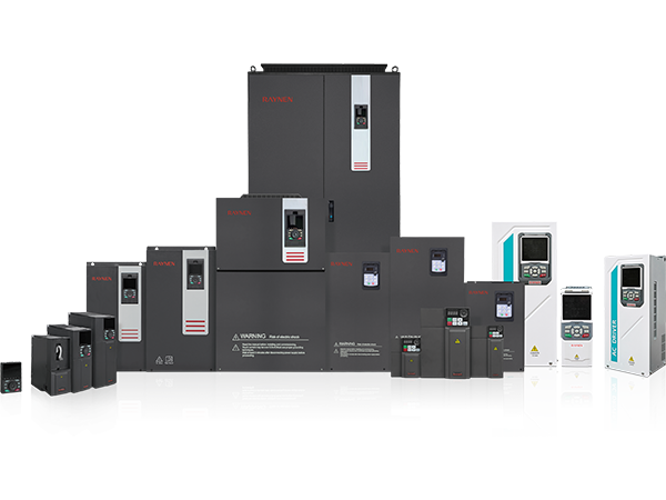
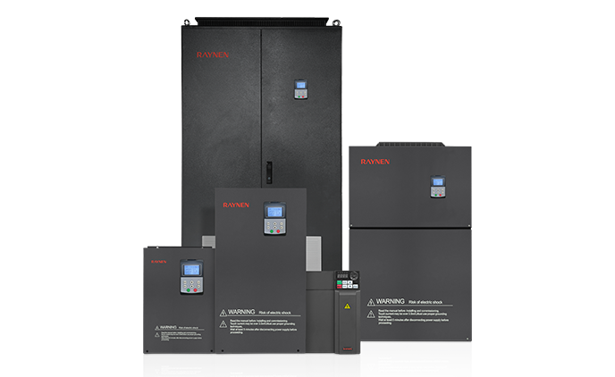
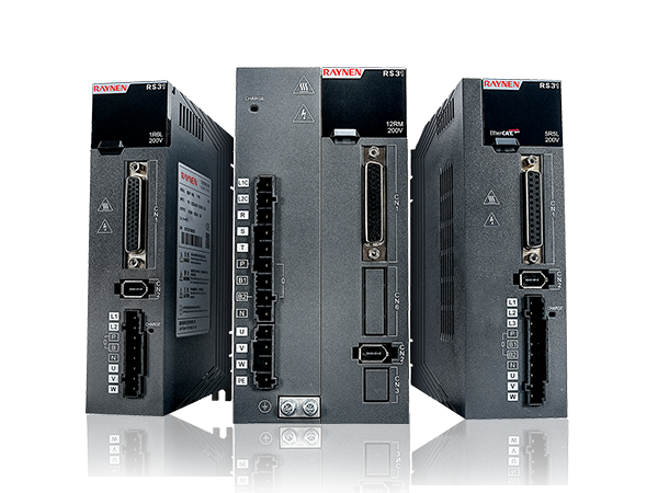


1.Introduction to AC Drives (Variable Frequency Drives) In the realm of modern industrial control an......
READ MOREElectric Drive Explained: How It Works, Types, and Why It Matters
Content
- 1 What Is an Electric Drive and How Does It Work?
- 2 Core Components of an Electric Drive System
- 3 Main Types of Electric Drive Systems
- 4 Electric Drive in Electric Vehicles: How Automotive Traction Works
- 5 Industrial Electric Drive Applications and Energy Savings
- 6 Key Specifications to Understand When Selecting an Electric Drive
- 7 Electric Drive vs. Hydraulic Drive vs. Mechanical Drive: A Practical Comparison
- 8 Installing and Commissioning an Electric Drive System: What to Get Right
- 9 The Future of Electric Drive Technology
What Is an Electric Drive and How Does It Work?
An electric drive is a system that uses electrical energy to control the speed, torque, and direction of a motor-driven mechanical load. At its most fundamental level, an electric drive consists of three core elements: a power source, a power conversion unit (such as a frequency inverter or motor controller), and an electric motor that converts electrical energy into mechanical motion. The drive system governs how electrical energy is delivered to the motor, allowing precise, efficient, and responsive control over the output — whether that output is turning a conveyor belt, spinning a pump impeller, accelerating a vehicle, or driving a robotic arm.
What distinguishes a modern electric drive from simply connecting a motor directly to a power supply is the intelligence embedded in the control unit. A direct-on-line motor connection delivers full voltage and frequency immediately, giving the motor no choice but to operate at one fixed speed with no ability to modulate torque or adapt to changing load conditions. An electric drive system inserts a programmable controller between the power supply and the motor, enabling continuous real-time adjustment of voltage, current, and frequency based on feedback signals from sensors monitoring speed, load, temperature, and position. This controllability is the defining advantage of electric drive technology over fixed-speed mechanical alternatives.
Core Components of an Electric Drive System
Understanding what makes up an electric drive system is essential for anyone specifying, commissioning, or maintaining one. While specific architectures vary by application, most electric drive systems share a common set of functional components that work together to deliver controlled mechanical output.
Power Supply and Rectifier Stage
In AC-powered electric drive systems, the incoming alternating current from the grid is first converted to direct current by a rectifier circuit. This DC bus stage stores energy in capacitors and provides a stable intermediate voltage that the drive's inverter stage can then modulate into the precise output waveform the motor requires. The quality of this rectification stage directly affects the drive's harmonic distortion characteristics and its compatibility with the power grid. High-performance electric drives incorporate active front-end rectifiers that both reduce harmonics injected back into the supply and enable regenerative braking — feeding energy back to the grid when the motor decelerates.
Inverter and PWM Control
The inverter is the heart of the variable speed electric drive. It takes the DC bus voltage and uses a bank of switching transistors — typically insulated gate bipolar transistors (IGBTs) — to reconstruct a variable-frequency, variable-voltage AC output through a technique called pulse width modulation (PWM). By rapidly switching the transistors on and off thousands of times per second, the drive synthesizes a smooth, controllable AC waveform that the motor interprets as a genuine sinusoidal supply. Changing the output frequency changes the motor speed; changing the output voltage in proportion to frequency maintains constant motor flux and torque capacity across the speed range. The switching frequency of the PWM inverter — typically between 2 kHz and 16 kHz — affects both the audible noise produced by the motor and the switching losses in the drive itself.
Motor Control Processor and Feedback Loop
The microprocessor or DSP (digital signal processor) in an electric drive executes the control algorithm that translates a speed or torque setpoint into precise inverter switching commands. In simpler scalar (V/f) control drives, the processor maintains a fixed voltage-to-frequency ratio and responds relatively slowly to load changes. In more sophisticated vector control or direct torque control (DTC) drives, the processor continuously calculates the instantaneous position and magnitude of the motor's magnetic flux and torque-producing current components, enabling sub-millisecond response to dynamic load changes. Feedback to the processor comes from current sensors within the drive and optionally from an external encoder or resolver mounted on the motor shaft for precise position and speed measurement.
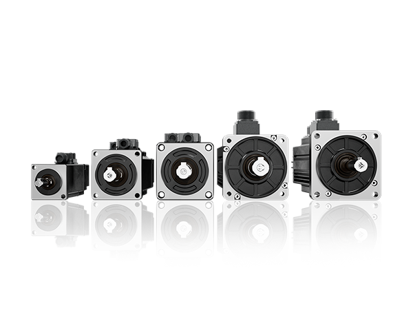
The Electric Motor
The motor is the output device of the electric drive system, converting the controlled electrical energy from the drive into mechanical shaft rotation. The most common motor type used with variable speed electric drives is the three-phase induction motor (also called an asynchronous motor), which is robust, low-maintenance, and available in an enormous range of power ratings and frame sizes. Permanent magnet synchronous motors (PMSMs) are increasingly used in both industrial and automotive electric drive applications where high power density, high efficiency across a wide speed range, and compact size are priorities. Switched reluctance motors and wound-rotor synchronous motors are used in specialized high-power or harsh-environment electric drive applications.
Main Types of Electric Drive Systems
Electric drive technology encompasses several distinct system architectures, each suited to different performance requirements, motor types, and application environments. The table below summarizes the principal types of electric drives and their key characteristics.
| Drive Type | Motor Compatibility | Control Method | Typical Applications |
| Variable Frequency Drive (VFD) | AC induction, PMSM | V/f scalar, vector control | Pumps, fans, conveyors, HVAC |
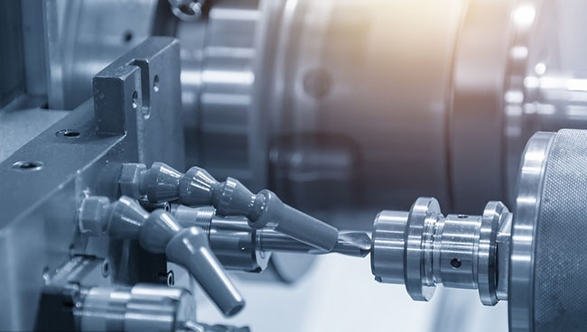
| Servo Drive | PMSM, brushless DC | Closed-loop vector, encoder feedback | CNC machines, robotics, packaging |
| DC Drive | DC brushed motor | Thyristor/SCR phase control | Legacy industrial, cranes, extruders |
| Stepper Drive | Stepper motor | Open-loop step/direction | 3D printers, plotters, small positioning |
| Traction Drive (EV) | PMSM, induction motor | Field-oriented control (FOC) | Electric vehicles, e-bikes, trains |
| Regenerative Drive | AC induction, PMSM | Active front end, four-quadrant | Elevators, test rigs, wind turbines |
Electric Drive in Electric Vehicles: How Automotive Traction Works
The electric drive unit in a battery electric vehicle (BEV) is one of the most performance-critical and technically sophisticated applications of electric drive technology in existence today. An automotive electric drive system must deliver smooth, instantaneous torque from rest, sustain high power output for extended periods, operate efficiently across an enormous speed range, survive decades of vibration and temperature cycling, and fit within extremely tight packaging constraints — all simultaneously.
How an EV Traction Drive Works
In a battery electric vehicle, the high-voltage battery pack (typically 400V or 800V) supplies DC power to the traction inverter, which converts it to three-phase AC at the frequency and voltage required to produce the driver-commanded torque. The traction inverter uses field-oriented control (FOC) to independently regulate the flux-producing and torque-producing current components in the motor, enabling precise torque delivery even at very low speeds. The motor output shaft connects to a single-speed reduction gearbox — electric motors produce useful torque across a very wide speed range, eliminating the need for a multi-speed transmission — and from there to the driven wheels via a differential or, in some architectures, via individual in-wheel motors.
Regenerative Braking in EV Electric Drives
One of the most significant energy efficiency advantages of electric drive systems in vehicles is regenerative braking. When the driver lifts off the accelerator or applies the brakes, the traction drive commands the motor to operate as a generator, converting the vehicle's kinetic energy back into electrical energy and feeding it back into the battery. The inverter operates in reverse energy flow, with the motor now producing a braking torque while acting as an electrical source. In urban driving cycles with frequent acceleration and deceleration, regenerative braking can recover 15% to 25% of the total energy used, significantly extending range compared to what would be achieved with friction braking alone.
Single Motor vs. Dual Motor and All-Wheel-Drive Configurations
Entry-level electric vehicles typically use a single electric drive unit driving either the front or rear axle. Dual-motor configurations — with one drive unit per axle — provide all-wheel drive capability and allow the vehicle management system to independently control torque on each axle for superior traction and dynamics. Some high-performance EVs use three or even four individual drive units, one per wheel, enabling torque vectoring with a degree of precision that no mechanical differential system can match. The independent controllability of each electric drive unit is a fundamental advantage that electrified drivetrains have over conventional mechanical systems.
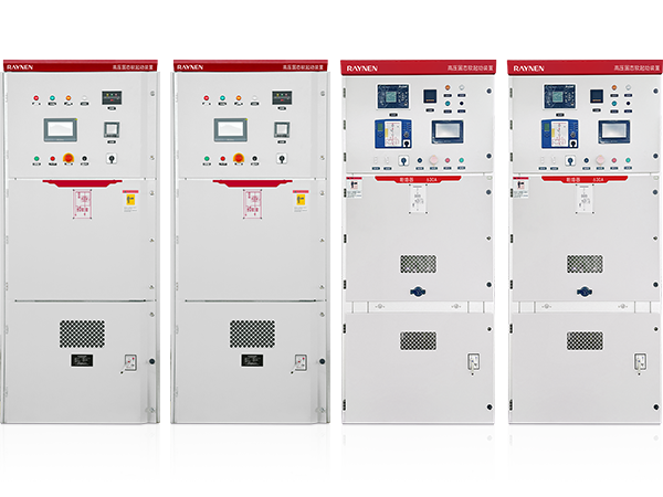
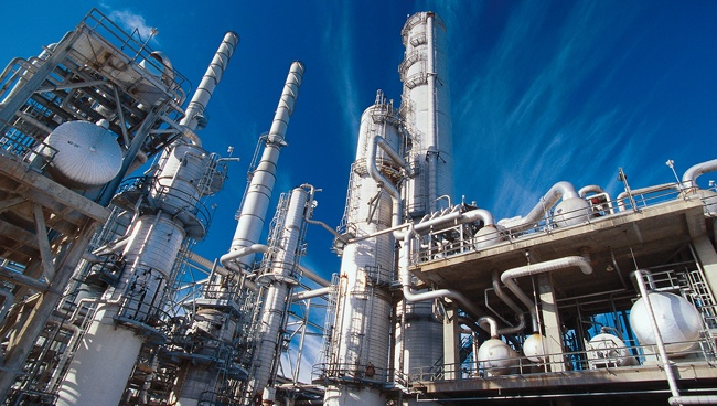
Industrial Electric Drive Applications and Energy Savings
Industrial electric drives — primarily variable frequency drives controlling AC induction motors — account for a substantial portion of global industrial electricity consumption. According to the International Energy Agency, electric motor systems consume roughly 45% of all electricity generated worldwide, and the majority of that consumption is in industrial settings. Replacing fixed-speed direct-on-line motor starters with variable speed electric drives offers some of the most cost-effective energy savings available in industrial operations.
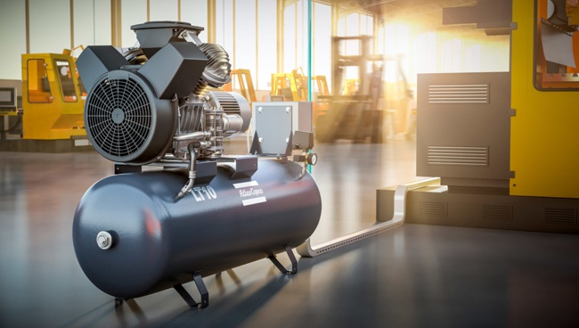
The Affinity Laws: Why Speed Control Saves So Much Energy
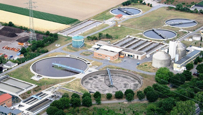
For centrifugal loads — pumps, fans, compressors, and blowers — the relationship between motor speed and power consumption follows the affinity laws: power consumption is proportional to the cube of the speed ratio. This means that reducing a pump motor's speed from 100% to 80% of full speed reduces its power consumption to approximately 51% of its full-speed value (0.8³ = 0.512). Reducing speed to 60% cuts consumption to just 22% of full speed. In pumping and HVAC systems where flow demand varies throughout the day or year, replacing a fixed-speed motor drive with a variable speed electric drive can reduce energy consumption by 30% to 60% with payback periods frequently under two years at typical industrial electricity tariffs.
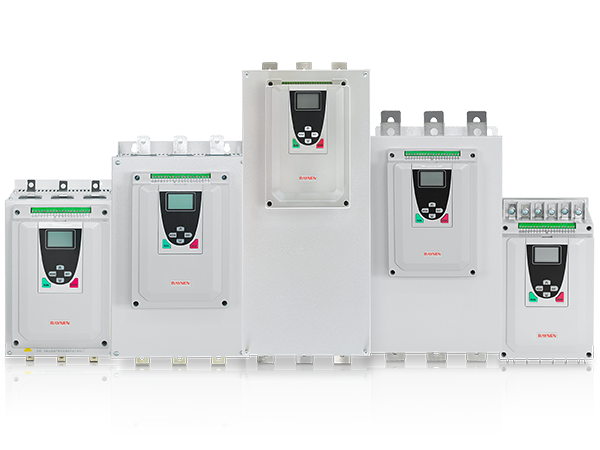
Soft Starting and Reduced Mechanical Stress
Beyond energy savings, variable speed electric drives protect both the motor and the driven mechanical system by eliminating the high inrush current and shock torque associated with direct-on-line starting. When a motor is started direct-on-line, it draws six to ten times its full-load current for the first few seconds and applies an impulsive torque spike to the mechanical system. Over time, this repeated mechanical shock fatigue-loads couplings, gearboxes, conveyor belts, pipe joints, and pump impellers. Starting through an electric drive — ramping speed up smoothly over a programmable acceleration ramp — reduces peak starting current to 100% to 150% of full-load current and eliminates the torque spike entirely, measurably extending the service life of the entire drive train.

Key Specifications to Understand When Selecting an Electric Drive
Whether you are selecting an industrial variable speed drive for a pump application or evaluating the electric drive system in a vehicle, the following specifications are the most important to understand and match to your application requirements.
- Power rating (kW or hp): The continuous output power rating of the drive must equal or exceed the full-load power requirement of the motor it will control. Most drives also specify an overload capacity — such as 150% of rated current for 60 seconds — which must be sufficient for the acceleration torque demands of the application.
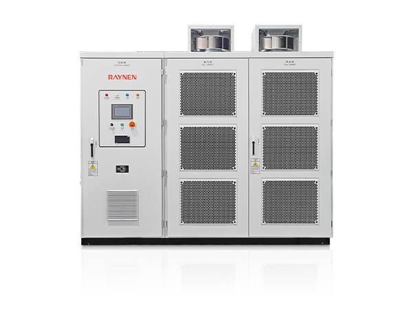
- Input voltage and frequency: Drives are designed for specific input voltage ranges (e.g., 200–240V single-phase, 380–480V three-phase, 690V three-phase) and input frequency (50 Hz or 60 Hz). Matching the drive to the available supply voltage is essential; most modern drives accept a ±10% voltage tolerance and accommodate both 50 Hz and 60 Hz supply frequencies.
- Output frequency range: For variable speed applications, the drive's output frequency range determines the motor speed range it can deliver. A typical industrial VFD outputs 0 Hz to 500 Hz or higher, providing a speed range far wider than any mechanical speed adjustment system. The minimum controllable speed without losing torque capability is equally important for applications requiring stable low-speed operation.
- Control mode (V/f, open-loop vector, closed-loop vector): V/f scalar control is adequate for simple centrifugal load applications with no precision speed or torque requirements. Open-loop vector control (sensorless vector) provides improved low-speed torque and dynamic response without an encoder. Closed-loop vector control with encoder feedback delivers the highest dynamic performance and speed accuracy, necessary for positioning applications and high-inertia loads requiring rapid torque response.
- Environmental protection rating (IP rating): The IP (Ingress Protection) rating of the drive enclosure specifies its resistance to dust and water ingress. IP20 drives are suitable for clean, dry control panels. IP54 or IP55 drives are used in dusty or splash-prone industrial environments. IP66 or higher is required for outdoor installations or washdown environments in food processing and similar sectors.
- Communication interfaces: Modern electric drives support a range of industrial communication protocols for integration with PLCs and supervisory control systems. Common interfaces include Modbus RTU/TCP, PROFIBUS, PROFINET, EtherNet/IP, CANopen, and EtherCAT. Selecting a drive with the correct protocol for your automation system avoids expensive gateway hardware and simplifies commissioning and diagnostics.
- Braking capability: Applications with high-inertia loads or frequent deceleration cycles — such as centrifuges, hoists, cranes, and test stands — require a drive with either a built-in braking transistor and external braking resistor for dynamic braking (dissipating braking energy as heat) or an active front-end regenerative drive that feeds braking energy back to the supply grid for maximum efficiency.
Electric Drive vs. Hydraulic Drive vs. Mechanical Drive: A Practical Comparison
In many industrial and mobile equipment applications, electric drive systems compete directly with hydraulic and mechanical drive alternatives. Each technology has genuine strengths and weaknesses, and the right choice depends on the specific demands of the application. The comparison below highlights the key practical differences.
| Criteria | Electric Drive | Hydraulic Drive | Mechanical Drive |
| Efficiency | High (85–97%) | Moderate (60–80%) | High (fixed ratio) |
| Speed controllability | Excellent (wide range) | Good | Limited (fixed or stepped) |
| Power density | High (PMSM) | Very high | Moderate |
| Maintenance | Low | High (seals, fluid, filters) | Moderate (lubrication, wear parts) |
| Cleanliness | Clean, no fluid risk | Leak and fire risk | Clean |
| Noise level | Low to moderate | High (pump, valve noise) | Moderate |
| Remote controllability | Excellent | Moderate | Poor |
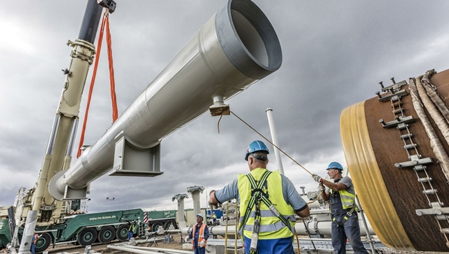
Installing and Commissioning an Electric Drive System: What to Get Right
Even the best electric drive system will underperform or fail prematurely if it is incorrectly installed or commissioned. The following points cover the most critical installation and setup considerations for industrial electric drives.
Thermal Management and Ventilation
Electric drives generate heat during operation — primarily from switching losses in the inverter IGBTs and conduction losses in the power circuit. Most drives are designed to operate within an ambient temperature range of 0°C to 40°C (32°F to 104°F) at full rated current. Above 40°C ambient, the drive must be derated — operated at reduced output current — to keep internal component temperatures within safe limits. Ensure the drive is mounted in a location with adequate air circulation, the required clearance above and below the unit for cooling airflow as specified in the manufacturer's installation manual, and that the control panel or enclosure has sufficient ventilation or forced-air cooling for the total heat dissipation of all installed drives.
Motor Cable Length and EMC Filtering
The PWM output waveform of a variable speed electric drive contains high-frequency voltage components that can cause problems over long cable runs to the motor. Voltage reflection effects in long motor cables (typically defined as exceeding 50 meters for drives without output reactors) can cause peak voltages at the motor terminals significantly higher than the drive's DC bus voltage, stressing the motor winding insulation. For cable runs exceeding the drive manufacturer's stated limit without mitigation, install an output reactor (also called a motor choke) or a dV/dt filter at the drive output. In addition, ensure that the motor cable is screened (shielded) with the screen bonded to earth at both the drive and motor ends, and that the motor cable is routed separately from signal and control cables to minimize electromagnetic interference (EMI).
Parameter Setup and Motor Identification
Before commissioning an electric drive for the first time, enter the motor nameplate data — rated voltage, rated current, rated frequency, rated speed, and motor power factor — into the drive's parameter set. Most modern drives include an automated motor identification or auto-tune routine that runs the motor through a controlled test sequence and measures the actual electrical characteristics of the connected motor, optimizing the drive's internal control parameters for that specific motor. Running the auto-tune routine before putting the system into service is strongly recommended, particularly for vector control drives, as it significantly improves speed regulation accuracy and dynamic torque response compared to relying on estimated motor parameters from the nameplate alone.
The Future of Electric Drive Technology
Electric drive technology is advancing rapidly on multiple fronts, driven by the electrification of transportation, increasing automation in industry, and the global push to reduce energy consumption and carbon emissions. Several key developments are shaping the next generation of electric drive systems.
- Wide bandgap semiconductors (SiC and GaN): Silicon carbide (SiC) and gallium nitride (GaN) power transistors are replacing conventional silicon IGBTs in high-performance electric drives. These wide bandgap devices switch faster, operate at higher temperatures, and have lower switching losses than silicon, enabling drives that are smaller, lighter, more efficient, and capable of higher switching frequencies. SiC inverters are now standard in premium electric vehicle traction drives and are rapidly entering industrial drive products.
- Integrated motor-drive units: Mounting the drive electronics directly on or inside the motor housing — creating an integrated motor-drive unit — eliminates the long motor cable run, reduces EMI, improves system efficiency, and simplifies installation. Integrated electric drive motors are gaining traction in pump and fan applications, HVAC systems, and electric vehicle auxiliary systems.
- AI and predictive maintenance: Modern electric drives generate a continuous stream of operational data — current, voltage, speed, temperature, vibration, and fault history. Artificial intelligence and machine learning algorithms applied to this data can detect subtle changes in motor or load behavior that precede failures by weeks or months, enabling predictive maintenance interventions that prevent unplanned downtime. Cloud-connected drives with built-in condition monitoring are increasingly standard in industrial automation platforms.
- Higher voltage architectures in EVs: Automotive electric drive systems are transitioning from 400V to 800V battery architectures, which reduces the current required for a given power level, allowing thinner, lighter wiring harnesses and enabling much faster DC fast charging. The 800V electric drive architecture, pioneered by Porsche and Hyundai/Kia, is becoming the new standard for long-range premium electric vehicles and is expected to become widespread across all EV segments within the next several years.
- Grid-interactive and vehicle-to-grid (V2G) drives: Bidirectional electric drive systems capable of exporting power from an EV battery back to the electricity grid or to a building's electrical system are moving from demonstration projects to commercial deployment. V2G-capable electric drives allow EV batteries to act as distributed energy storage assets, providing grid stability services and enabling EV owners to earn revenue by selling stored energy at peak demand periods.
Previous Post
Variable Frequency Drive Explained: How It Works and When You Actually Need One
Next Post
Low-Voltage Soft Starter: How It Works, When to Use It, and How to Choose the Right One
Copyright 2024 Fujian Raynen Technology Co.,Ltd. All Rights Reserved.
Privacy Policy  Motor Control Manufacturers