English
 Español
 عربى
عربى
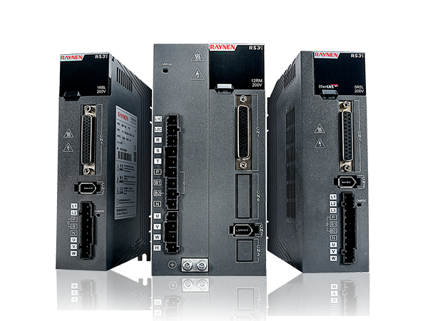


1.Introduction to AC Drives (Variable Frequency Drives) In the realm of modern industrial control an......
READ MOREHome / News / Industry News / Variable Frequency Drive Explained: How It Works and When You Actually Need One
Variable Frequency Drive Explained: How It Works and When You Actually Need One
Content
- 1 What a Variable Frequency Drive Actually Does
- 2 How a VFD Works Internally: The Three-Stage Power Conversion Process
- 3 Types of Variable Frequency Drives and Where Each One Is Used
- 4 Real-World Applications: Where Variable Speed Drives Deliver the Most Value
- 5 Energy Savings Calculations: How to Estimate VFD ROI Before You Buy
- 6 Key Parameters to Specify When Selecting a VFD
- 7 Common VFD Problems and How to Troubleshoot Them
- 8 VFD Installation Best Practices That Prevent Most Field Problems
What a Variable Frequency Drive Actually Does
A variable frequency drive (VFD) is an electronic controller that adjusts the speed of an AC electric motor by varying the frequency and voltage of the power supplied to it. Rather than running a motor at a fixed speed determined by line frequency — typically 50 Hz or 60 Hz depending on the country — a VFD allows the motor to run at precisely the speed the application requires at any given moment. This seemingly simple capability has profound implications for energy consumption, mechanical wear, process control, and operational flexibility across virtually every industry that uses electric motors.
To understand why this matters, consider a pump moving fluid through a pipe. A motor running at fixed full speed delivers maximum flow regardless of whether maximum flow is actually needed. Historically, the only way to reduce flow was to partially close a valve — wasting the energy that was still being consumed to push fluid against the restriction. A VFD solves this by simply slowing the motor down when less output is required. Because power consumption in centrifugal loads like pumps and fans follows the cube law, reducing motor speed by just 20% cuts energy consumption by approximately 49%. That relationship is the core reason VFDs generate such rapid returns on investment in variable-load applications.
VFDs are also known by several other names depending on industry and region: variable speed drives (VSDs), adjustable frequency drives (AFDs), inverter drives, and AC drives all refer to essentially the same technology. In some contexts, the term "inverter" is used specifically — a reference to the final stage of the VFD's internal power conversion process.
How a VFD Works Internally: The Three-Stage Power Conversion Process
Understanding what happens inside a variable frequency drive clarifies why it performs as it does — and why certain installation and protection requirements exist. The conversion process takes place in three distinct stages: rectification, DC bus filtering, and inversion.
Stage 1: The Rectifier
Incoming AC power from the supply — whether single-phase or three-phase — enters the rectifier section first. The rectifier converts AC voltage to DC voltage using a diode bridge or, in more advanced drives, a set of controlled thyristors or IGBTs (Insulated Gate Bipolar Transistors). A standard six-pulse diode rectifier is the most common configuration in industrial VFDs. The output of the rectifier is a pulsating DC voltage that still carries a significant AC ripple component.
Stage 2: The DC Bus
The pulsating DC from the rectifier passes through a DC bus — essentially a bank of large capacitors and sometimes inductors — that smooths the voltage into a stable DC level. This intermediate DC bus is typically at approximately 1.35 times the incoming line-to-line RMS voltage: around 650–700V DC for a 480V AC supply, or 270–310V DC for a 230V AC supply. The DC bus also serves as an energy storage buffer, absorbing the regenerative energy produced when the motor decelerates. In drives without a braking resistor or regenerative front end, this energy must be dissipated — which is why braking resistors are required in applications with high-inertia loads that stop frequently.
Stage 3: The Inverter
The inverter section converts the stable DC voltage back into a synthetic AC output with variable frequency and amplitude. Modern VFDs accomplish this using IGBT switching transistors controlled by Pulse Width Modulation (PWM). The IGBTs switch on and off at high frequency — typically 2 to 16 kHz — creating a series of pulses whose width varies in a pattern that, when integrated over time, produces a sinusoidal waveform of the desired frequency and voltage. By adjusting the PWM pattern, the drive can produce output frequencies from near zero up to 400 Hz or more, corresponding to motor speeds from essentially stopped to several times base speed. The motor's inductance acts as a natural filter, converting the PWM pulse train into smooth sinusoidal current flow through the motor windings.
Types of Variable Frequency Drives and Where Each One Is Used
Not all VFDs are engineered the same way. Different drive topologies are optimized for specific application requirements, power ranges, and operational environments. Selecting the wrong type for the application creates problems that cannot be corrected through parameter adjustment alone.
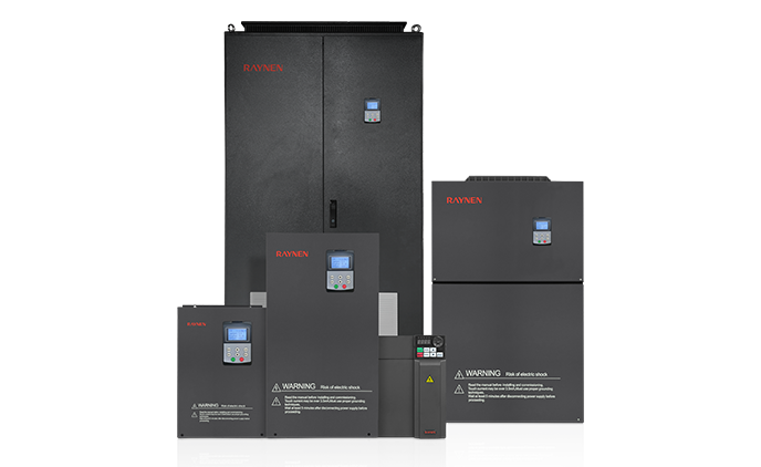
Voltage Source Inverter (VSI) Drives
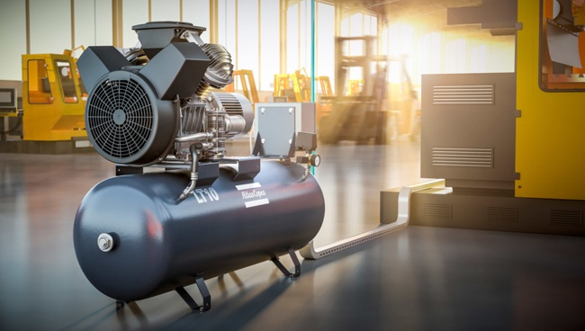
VSI drives — which include the vast majority of general-purpose VFDs sold today — regulate voltage on the DC bus and use PWM to generate a variable-frequency AC output. They are versatile, cost-effective, and available across a power range from fractional horsepower up to several megawatts. VSI drives are suitable for most pump, fan, conveyor, and compressor applications. Their primary limitation is that they produce a non-sinusoidal output that can cause additional heating in motor windings — particularly relevant for older motors not designed with inverter duty ratings.
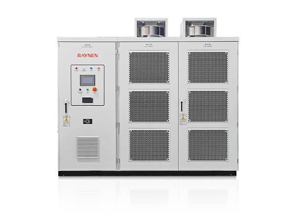
Current Source Inverter (CSI) Drives
CSI drives regulate current rather than voltage on the DC bus. They are inherently capable of regenerative braking — returning braking energy back to the supply grid — without additional hardware. CSI drives are typically used in high-power applications above 500 kW, such as large compressors, mine hoists, and industrial mills, where their ability to handle very large motor currents and regenerate power economically justifies their higher cost and larger physical footprint.
Direct Torque Control (DTC) Drives
DTC is a control algorithm rather than a distinct hardware topology, but it represents a meaningful category distinction in drive selection. Instead of controlling motor speed by adjusting output frequency and voltage through a fixed PWM pattern, DTC drives continuously estimate motor flux and torque in real time and directly adjust inverter switching to control these quantities. The result is extremely fast torque response — ABB's DTC implementation achieves torque response times under 2 milliseconds — and accurate speed control without the need for an encoder on the motor shaft. DTC drives are used in demanding applications including paper machines, cranes, and winding equipment where torque precision and dynamic response are critical.
Regenerative VFDs
Standard VFDs dissipate braking energy as heat through a braking resistor. Regenerative drives use an active front-end rectifier that can return this energy to the supply grid as usable AC power. In applications where the motor decelerates heavy loads frequently — elevators, dynamometer test stands, downhill conveyors — the energy that would be wasted as heat can instead represent 15 to 40% of total drive energy consumption, making regenerative drives economically compelling despite their higher initial cost.
| VFD Type | Typical Power Range | Key Advantage | Best Application |
|---|---|---|---|
| Voltage Source Inverter (VSI) | 0.1 kW – 2 MW+ | Cost-effective, versatile | Pumps, fans, conveyors, HVAC |
| Current Source Inverter (CSI) | 500 kW – 100 MW | Native regeneration, high power | Large compressors, mine hoists |
| Direct Torque Control (DTC) | 0.5 kW – 5 MW+ | Fast torque response, no encoder needed | Cranes, winders, paper machines |
| Regenerative Active Front End | 7.5 kW – 1 MW+ | Returns braking energy to grid | Elevators, test rigs, downhill conveyors |
Real-World Applications: Where Variable Speed Drives Deliver the Most Value
VFDs are installed across an enormous range of industries and applications, but their value is not uniform across all of them. The strongest cases for VFD deployment share specific characteristics: variable load demand, high annual run hours, and centrifugal or variable-torque load profiles.
HVAC Systems: Fans and Pumps
Heating, ventilation, and air conditioning systems represent the single largest application segment for VFDs globally. Supply air fans, return air fans, chilled water pumps, condenser water pumps, and cooling tower fans all operate as variable-load centrifugal applications. A commercial building's HVAC system rarely requires full design capacity — full load operation may represent only 1 to 5% of annual operating hours. VFDs on HVAC fans and pumps typically reduce annual energy consumption for those motors by 30 to 60% compared to fixed-speed operation with damper or valve throttling. Payback periods in commercial HVAC retrofits commonly fall between 1.5 and 3 years.
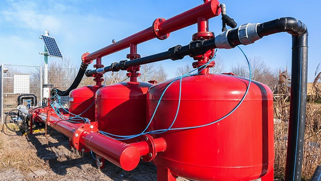
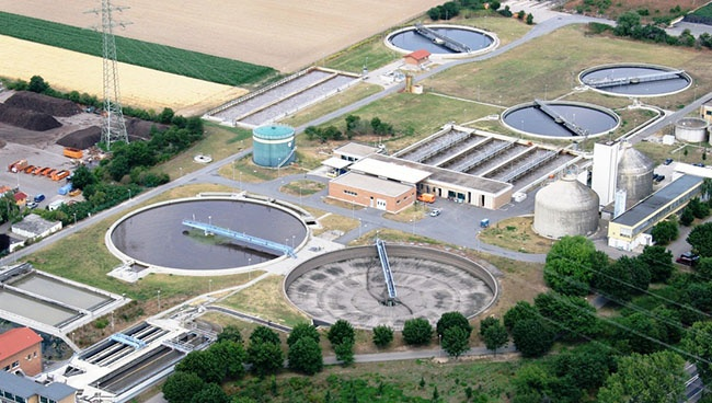
Water and Wastewater Treatment
Municipal water distribution systems use VFDs on booster pump stations to maintain constant system pressure regardless of demand fluctuations throughout the day. Without drives, fixed-speed pumps cycle on and off to maintain pressure — creating water hammer, accelerated valve wear, and pressure transients that stress pipe infrastructure. A VFD-controlled pump running continuously at variable speed maintains more stable pressure, eliminates water hammer, and reduces motor starts from potentially hundreds per day to a continuous low-speed operation cycle. Wastewater aeration blowers also benefit significantly: aeration represents approximately 50 to 60% of a wastewater treatment plant's total energy budget, and VFD control of blowers to match dissolved oxygen demand rather than running at fixed output generates substantial utility savings.
Manufacturing and Process Industries
In manufacturing, VFDs provide precise speed control for conveyors, mixers, extruders, and machine tool spindles. A packaging line conveyor running at a speed precisely matched to upstream process output avoids product accumulation and reduces mechanical stress on the conveyor structure. Extruder screws controlled by VFDs allow processors to dial in exact output rates and respond to material viscosity changes in real time. In the textile industry, fiber processing machinery requires speed coordination across multiple axes — VFDs connected to a supervisory control system maintain the precise speed ratios that determine fiber tension and quality.
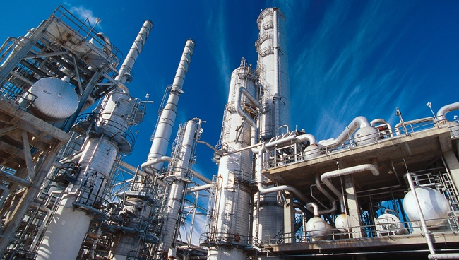
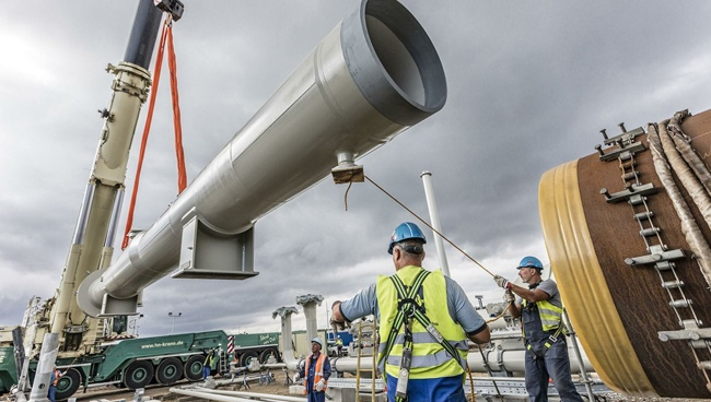
Oil and Gas Extraction and Pipeline
Electric Submersible Pumps (ESPs) used in oil well production operate in highly variable conditions as reservoir pressure and fluid composition change over the well's producing life. VFD control of ESPs allows production to be optimized continuously rather than accepting fixed-speed output that may over-pump or under-pump relative to reservoir inflow. On pipeline compressor stations, variable speed drives on gas compressors allow discharge pressure to be maintained precisely across varying inlet conditions and flow demands — replacing mechanical throttling that wastes compression energy and increases valve maintenance costs.
Energy Savings Calculations: How to Estimate VFD ROI Before You Buy
The business case for a VFD investment should be quantified before purchase, not assumed. The calculation is straightforward for centrifugal loads and requires only a few known values: motor rated power, annual operating hours, average load profile, and local electricity cost.
For a centrifugal pump or fan, the affinity laws describe the relationship between speed and power consumption precisely:
- Flow varies linearly with speed: reducing speed by 20% reduces flow by 20%.
- Pressure varies with the square of speed: reducing speed by 20% reduces pressure by 36%.
- Power varies with the cube of speed: reducing speed by 20% reduces power consumption by approximately 49%.
As a worked example: a 75 kW centrifugal pump motor running 6,000 hours per year at an average of 80% speed consumes approximately 75 × (0.8)³ × 6,000 = 230,400 kWh per year, compared to 75 × 6,000 = 450,000 kWh per year at fixed full speed. At an electricity rate of $0.10/kWh, the annual saving is approximately $21,960. If the VFD costs $8,000 installed, the simple payback period is under 4.5 months — a return that almost no other capital investment can match in industrial settings.
For constant-torque loads like conveyors and positive displacement pumps, the cubic relationship does not apply — power scales more linearly with speed. VFDs still deliver value in these applications through soft starting, process precision, and reduced mechanical wear, but the energy savings calculation must reflect the actual load characteristic rather than assuming centrifugal behavior.
Key Parameters to Specify When Selecting a VFD
Selecting a variable frequency drive involves more than matching the motor's kilowatt or horsepower rating. A drive specified correctly for the application will perform reliably for decades; one specified incorrectly may fail prematurely, trip on faults under normal operation, or cause motor damage. The following parameters should be confirmed before ordering.
Current Rating vs. Power Rating
Always size a VFD by its output current rating in amps, not simply by kilowatts or horsepower. The motor nameplate full-load amperage (FLA) must fall at or below the VFD's continuous output current rating. For applications with high starting torque demands or frequent acceleration cycles, look at the drive's overload current rating — typically expressed as a percentage of continuous rating for a defined duration, such as 150% for 60 seconds. Applications requiring very high starting torque (crushers, loaded conveyors) may need a drive rated for heavy-duty duty cycle with 150–200% overload rather than normal-duty cycle.
Input Voltage and Phase
Confirm the available supply voltage and phase count at the installation point: single-phase 120V, single-phase 230V, three-phase 230V, three-phase 460/480V, or three-phase 575/600V are the most common in North American installations. European and Asian installations predominantly use 400V or 415V three-phase. Single-phase input drives are available up to approximately 4 kW (5 hp) — above this power level, three-phase supply is required. Operating a three-phase VFD from single-phase supply by connecting only two input terminals is possible as a temporary measure but results in significant DC bus ripple, reduced output capacity, and accelerated capacitor degradation — it is not a recommended long-term practice.
Enclosure Rating and Environment
VFD enclosure ratings must match the installation environment. IP20 or NEMA 1 (vented, finger-safe) enclosures are appropriate for clean, climate-controlled electrical rooms. IP54 or NEMA 12 (dust-tight, splash-resistant) is needed for industrial floors with airborne contaminants. IP55 or NEMA 4 (washdown-resistant) is required in food processing, pharmaceutical, and outdoor applications where the drive may be exposed to direct water spray. Installing an IP20 drive in a dusty or wet environment is one of the most common causes of premature drive failure — the cost difference between enclosure ratings is negligible compared to the cost of drive replacement and production downtime.
Motor Cable Length and Output Filtering
Long motor cables between a VFD and the motor create voltage reflection phenomena at the motor terminals — fast-rising PWM voltage pulses reflect off the cable-motor impedance discontinuity and can produce peak voltages at the motor terminals significantly exceeding the drive's DC bus voltage. As a general guideline, when motor cable lengths exceed 50 meters (approximately 150 feet), an output dV/dt filter or sine wave filter should be installed between the drive and the motor to protect motor winding insulation. This is particularly important for older motors not rated for inverter duty service, which have thinner winding insulation than modern inverter-rated designs.
Common VFD Problems and How to Troubleshoot Them
Even well-specified and correctly installed drives encounter operational issues. Most faults are repeatable and diagnosable from the drive's fault history log combined with knowledge of the application conditions at the time of the fault.
Overcurrent Faults
Overcurrent trips occur when the motor draws more current than the drive's overcurrent threshold — typically set at 150–200% of rated current. The most common causes are acceleration ramp times set too short for the connected load inertia, mechanical binding or jamming in the driven equipment, incorrect motor parameters programmed into the drive, or a failing motor with shorted winding turns drawing excess current. Check the fault log timestamp against process conditions, verify acceleration ramp settings against the load's actual inertia requirements, and confirm motor nameplate parameters are correctly entered in the drive setup.
Overvoltage Faults on Deceleration
When a motor decelerates, it acts as a generator, pushing energy back into the VFD's DC bus. If the deceleration rate is faster than the DC bus capacitors can absorb or the braking resistor can dissipate, DC bus voltage rises until the drive trips on overvoltage. The fix is usually to extend the deceleration ramp time, verify that an appropriately sized braking resistor is installed and functioning, or upgrade to a regenerative drive if frequent fast deceleration of high-inertia loads is an inherent application requirement.
Overtemperature Faults
VFDs generate heat from switching losses in the IGBT inverter stage — typically 3 to 5% of rated throughput power as heat. This heat must be removed by the drive's cooling system, which consists of internal heat sinks and forced-air cooling fans. Overtemperature faults indicate that the drive's internal temperature has exceeded its safe operating threshold. Common causes include blocked air vents or heat sink fins clogged with dust, ambient temperature in the enclosure exceeding the drive's rated maximum (typically 40–50°C), insufficient ventilation in a sealed enclosure, or a failed internal cooling fan. Regular cleaning of heat sink fins and verifying enclosure ventilation adequacy prevents most overtemperature faults.
Ground Fault Trips
Ground fault trips indicate current flowing from one or more motor phases to ground — most commonly through degraded motor winding insulation or damaged motor cable. Because VFD output contains high-frequency PWM components, leakage current through cable capacitance to ground is inherent and increases with cable length. Drives set with very sensitive ground fault thresholds may nuisance-trip on this leakage current in installations with long motor cables. If a ground fault trip cannot be correlated to actual insulation failure, check the drive's ground fault sensitivity setting and verify motor insulation resistance with a megohmmeter (minimum 1 MΩ at 500V DC is a standard acceptance threshold for motors in VFD service).
VFD Installation Best Practices That Prevent Most Field Problems
The majority of VFD field problems — nuisance trips, premature failures, interference with nearby equipment — trace back to installation errors rather than drive defects. Following established installation guidelines eliminates most of these issues before they occur.
- Use shielded motor cable. Shielded cable with the shield grounded at both ends contains the high-frequency common-mode currents generated by PWM switching and prevents them from radiating into adjacent signal wiring or control systems. Unshielded motor cable in VFD installations is the single most common cause of electromagnetic interference (EMI) complaints in industrial environments.
- Separate motor cables from control and signal cables. Route motor cables in dedicated conduit or cable tray, physically separated from instrumentation wiring, analog signal cables, and communication bus cables. A separation of at least 300 mm (12 inches) is the minimum; crossing at 90 degrees is acceptable where physical separation cannot be maintained.
- Install line reactors or input filters on large drives. Drives above approximately 15 kW draw non-sinusoidal current from the supply that introduces harmonic distortion into the power system — potentially causing overheating in transformers and capacitors and interfering with other sensitive equipment. A 3–5% impedance line reactor on the drive input substantially reduces harmonic injection and also provides protection against supply voltage transients.
- Maintain adequate clearances around the drive for airflow. Most drive manufacturers specify minimum clearances above, below, and on the sides of the drive for proper thermal management. Ignoring these clearances in a crowded panel layout creates hot spots that accelerate capacitor aging and reduce IGBT reliability.
- Do not install isolation contactors between the VFD output and the motor that open under load. Switching a contactor open while the VFD is supplying current creates a high-voltage arc and surge that can destroy output IGBTs instantly. If motor isolation is required for safety, always command the drive to ramp to zero speed before opening any output-side contactor.
- Commission the drive with the motor uncoupled from the load where possible. Running the motor solo at first allows parameter verification and rotation direction confirmation without risk of damaging the driven equipment if rotation is incorrect or if a fault causes an uncontrolled stop.
Previous Post
Programmable Logic Controller Explained: What It Is, How It Works, and How to Choose One
Next Post
Electric Drive Explained: How It Works, Types, and Why It Matters
Copyright 2024 Fujian Raynen Technology Co.,Ltd. All Rights Reserved.
Privacy Policy  Motor Control Manufacturers