English
 Español
 عربى
عربى
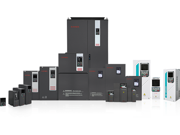
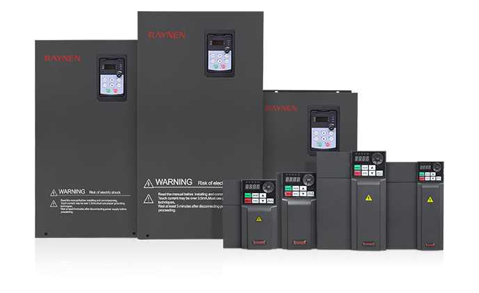
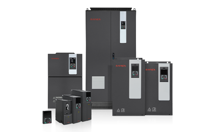
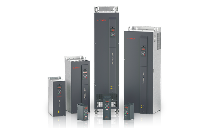
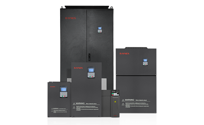
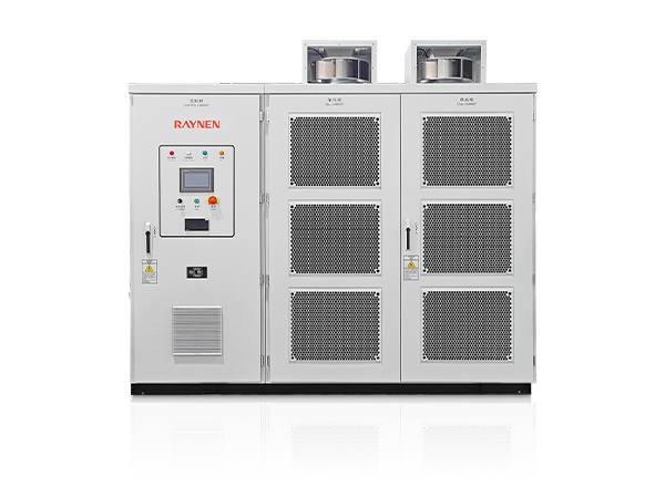
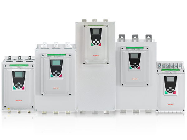
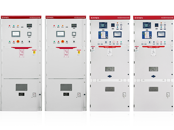
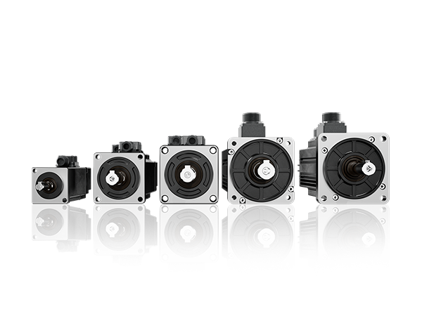
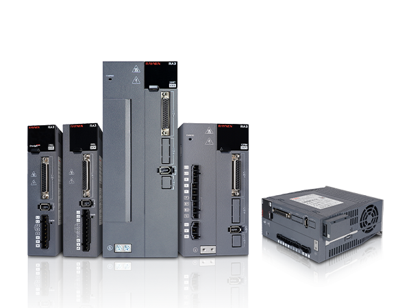
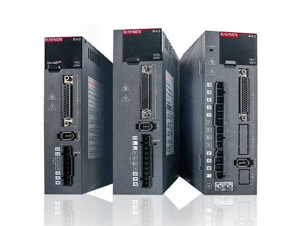
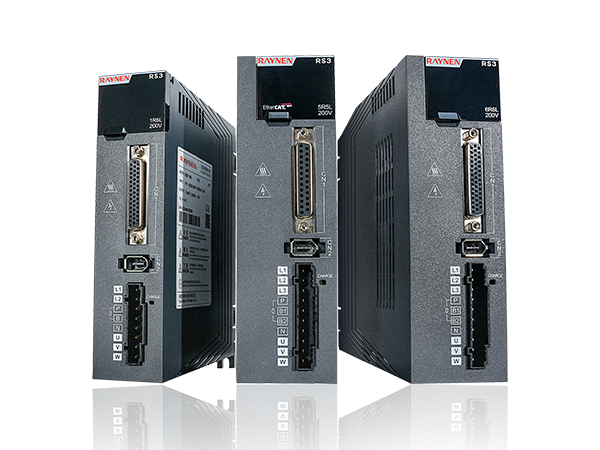
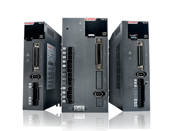









1.Introduction to AC Drives (Variable Frequency Drives) In the realm of modern industrial control an......
READ MOREHome / News / Industry News / Low-Voltage Variable Frequency Drive: Everything You Need to Know Before You Buy or Install One
Low-Voltage Variable Frequency Drive: Everything You Need to Know Before You Buy or Install One
Content
- 1 What a Low-Voltage Variable Frequency Drive Actually Does
- 2 Where Low-Voltage VFDs Are Used and Why They're So Widespread
- 3 Key Specifications to Understand Before Selecting an LV VFD
- 4 How to Size a Low-Voltage Variable Frequency Drive Correctly
- 5 Comparing Low-Voltage VFD Control Modes
- 6 Installation Best Practices for Low-Voltage Variable Frequency Drives
- 7 Energy Savings Potential: The Real Numbers Behind LV VFD Efficiency
- 8 Common Faults, Causes, and Troubleshooting for LV Variable Frequency Drives
- 9 LV VFD Communication and Integration with Modern Control Systems
- 10 What to Look for When Comparing LV VFD Brands and Models
What a Low-Voltage Variable Frequency Drive Actually Does
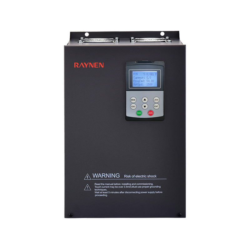
A low-voltage variable frequency drive — commonly abbreviated as LV VFD — is an electronic power control device that regulates the speed and torque of an AC induction motor by changing the frequency and voltage of the electrical supply delivered to it. Instead of running a motor at a fixed speed dictated by the grid frequency (50 Hz or 60 Hz depending on your region), a low-voltage VFD lets you dial in exactly how fast the motor spins, anywhere from near zero to full speed and sometimes beyond.
The "low-voltage" designation refers to the operating voltage range — typically below 1,000V AC, with the most common industrial ratings being 208V, 230V, 380V, 400V, 460V, and 480V. This distinguishes LV drives from medium-voltage VFDs, which operate above 1,000V and are used in larger, more specialized applications like large compressors, ship propulsion, and utility-scale pumping stations. The vast majority of commercial and industrial motor control applications fall squarely within the low-voltage category.
At its core, a low-voltage variable frequency drive works through a three-stage process: it first converts incoming AC power to DC through a rectifier stage, smooths that DC through a DC bus with capacitors, and then inverts it back to a variable-frequency AC output using insulated-gate bipolar transistors (IGBTs). This output mimics AC power at whatever frequency you command, which the motor reads as a corresponding rotational speed.
Where Low-Voltage VFDs Are Used and Why They're So Widespread
Low-voltage variable frequency drives appear in an enormous range of industries and applications. Their ability to precisely control motor speed while dramatically reducing energy consumption makes them one of the most impactful pieces of electrical equipment in modern industry. Once you understand what they do, you start seeing opportunities for them almost everywhere AC motors are used.
The most common application areas include:
- HVAC systems: Fans, air handling units, cooling tower fans, and chiller compressors are among the single largest consumers of electrical energy in commercial buildings. Variable speed drives allow these systems to match airflow and cooling output precisely to real-time demand rather than cycling on and off at full power.
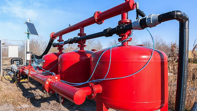
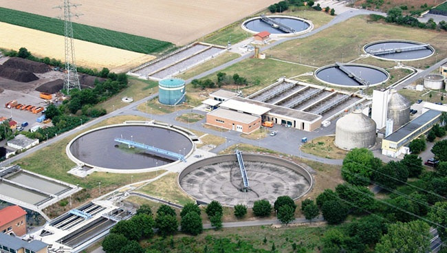
- Pumping systems: Water supply, wastewater treatment, irrigation, process fluid handling, and fire suppression systems all use centrifugal pumps that benefit enormously from variable speed control. Since pump power consumption follows the cube law, reducing speed by just 20% cuts power draw by nearly 50%.
- Conveyor and material handling: Manufacturing lines, warehouses, and packaging operations use LV VFDs to synchronize conveyor speeds, enable smooth product acceleration, and prevent mechanical shock loads that cause belt and drive component failures.
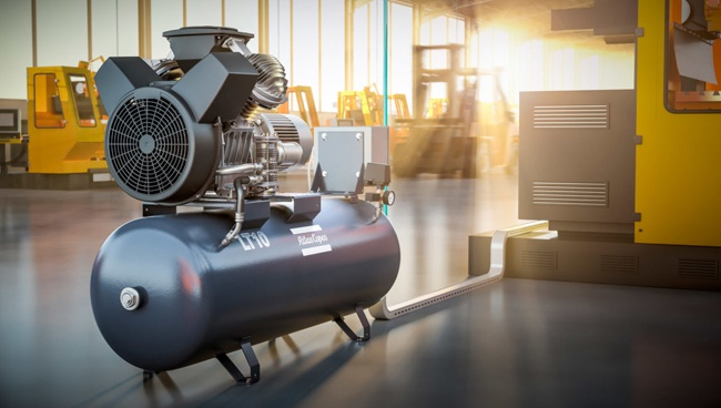
- Compressors: Both reciprocating and screw compressors in industrial compressed air systems benefit from VFD control, matching output pressure and volume to actual demand rather than running at fixed capacity with throttling or bypass waste.
- Machine tools and CNC equipment: Spindle drives, feed axes, and auxiliary systems in machining centers, lathes, and milling machines use low-voltage VFDs to enable precise programmable speed control and smooth acceleration profiles.
- Food and beverage processing: Mixers, extruders, bottling lines, and refrigeration systems require reliable, cleanable, and precisely controlled motor drives — an area where LV VFDs with appropriate enclosure ratings (IP54 or higher) excel.
Key Specifications to Understand Before Selecting an LV VFD
Choosing the wrong variable frequency drive for an application is a common and costly mistake. The datasheet for any LV VFD contains dozens of parameters, but a focused set of specifications matters most for correct selection. Understanding these before you talk to a supplier or place an order will save significant time and prevent misapplication.
Input Voltage and Phase
LV VFDs are available for both single-phase (1Ø) and three-phase (3Ø) input power. Single-phase input drives are typically available up to about 3–5 kW and are used in light-duty commercial or residential applications. Three-phase input drives cover the full range from fractional kilowatts to several hundred kilowatts and are the standard for industrial use. Always confirm whether your available supply is 208V, 230V, 380V, 400V, or 480V — the drive must be rated for your specific input voltage.
Output Power Rating (kW or HP)
The drive's output power rating must match or exceed the rated power of the motor it controls. However, correct sizing goes beyond matching the nameplate kW. You also need to account for the load type — a VFD driving a centrifugal pump (variable torque load) can often be sized at the motor's rated HP, while a VFD driving a crusher or hoist (constant or high-breakaway torque) may need to be oversized by one frame size to handle the higher current demands during starting and load peaks.
Output Current Rating
Current — not power — is what actually stresses a VFD's IGBTs and thermal management system. Always cross-check the drive's continuous output current rating against the motor's full-load amperage (FLA). For demanding applications, also check the drive's overload current capacity — typically expressed as 110% or 150% for 60 seconds, which protects against temporary load spikes without tripping on overcurrent.
Switching Frequency (Carrier Frequency)
The carrier frequency at which the IGBT switches operate — typically 2–16 kHz — affects motor noise, motor heating, and drive thermal load. Higher carrier frequencies produce a smoother, quieter output waveform that the motor "likes," but generate more heat within the drive itself. Many drives allow carrier frequency to be adjusted in commissioning to balance acoustic performance against drive temperature, sometimes requiring derating of the output current at higher settings.
Protection Rating (IP or NEMA Enclosure)
The drive's enclosure must suit the installation environment. IP20 or NEMA 1 is acceptable for clean, indoor control panels. IP54 or NEMA 12 suits dusty or lightly wet industrial environments. IP65 or NEMA 4 is required for wash-down or outdoor installations. Installing an IP20 drive in an environment that requires IP54 will result in contamination-related failures, voided warranties, and potential safety hazards.
How to Size a Low-Voltage Variable Frequency Drive Correctly
Proper sizing of a low-voltage AC drive is a systematic process, not a simple lookup. Follow these steps to arrive at a reliable selection:
- Identify the motor's nameplate data: Collect the motor's rated power (kW or HP), voltage, full-load amps (FLA), speed (RPM), frequency (Hz), and service factor. These are the baseline inputs for any drive selection.
- Classify the load type: Variable torque (fans, centrifugal pumps), constant torque (conveyors, positive displacement pumps, mixers), or high-inertia/high-breakaway torque (crushers, hoists, centrifuges). Load type determines overload requirements and whether to size up.
- Check the drive's output current vs. motor FLA: The drive's rated continuous output current must be equal to or greater than the motor's FLA. For constant torque loads, use a drive rated for 150% overload; for variable torque loads, 110% overload capacity is typically sufficient.
- Account for cable length derating: Long motor cables (above roughly 50 meters) increase voltage reflections and capacitive charging currents. Either derate the drive, use output reactors, or select a drive with built-in dV/dt filtering for long-cable installations.
- Consider ambient temperature derating: Most LV VFDs are rated for full output at 40°C ambient. Above that, output current must be derated — typically 1–3% per degree Celsius above the rated ambient. In hot control rooms or outdoor enclosures, this can require selecting a larger drive frame.
- Verify altitude derating if applicable: Air density decreases with altitude, reducing cooling efficiency. Above 1,000 meters (approximately 3,300 feet), most manufacturers require derating. Check the drive's altitude correction curve in the technical documentation.
Comparing Low-Voltage VFD Control Modes
Modern low-voltage variable speed drives offer multiple control modes, each suited to different application requirements. Understanding the differences helps you select both the right drive and configure it correctly during commissioning.
| Control Mode | How It Works | Best Application | Encoder Required? |
| V/Hz (Scalar) | Maintains fixed voltage-to-frequency ratio | Fans, pumps, simple variable torque loads | No |
| Open-Loop Vector (SVC) | Estimates flux and torque without feedback | Conveyors, mixers, general constant torque | No |
| Closed-Loop Vector (FOC) | Uses encoder feedback for precise torque/speed control | Hoists, winders, machine tools, positioning | Yes |
| Direct Torque Control (DTC) | Directly calculates and controls torque and flux | High-performance industrial processes | Optional |
For most pump and fan applications, V/Hz control is perfectly adequate and simpler to commission. Open-loop vector control is the go-to for general industrial conveyor and process applications where better low-speed torque and tighter speed regulation matter. Closed-loop vector and DTC are reserved for demanding applications requiring precise positioning, high starting torque at zero speed, or dynamic load response in the millisecond range.
Installation Best Practices for Low-Voltage Variable Frequency Drives
Incorrect installation is responsible for a large share of LV VFD failures and performance problems in the field. Following these installation guidelines significantly reduces the risk of nuisance trips, premature component failure, and EMI-related interference with surrounding equipment.
Grounding and Shielding
Proper grounding is non-negotiable with VFD installations. The drive's PE (protective earth) terminal must be connected to a low-impedance ground using a short, thick conductor — ideally a dedicated ground bar in the panel rather than a daisy-chained ground through other equipment. Use shielded motor cables with the shield terminated at both the drive output terminal and the motor terminal box using 360-degree EMC cable glands, not a pigtail. Pigtail terminations dramatically reduce the effectiveness of shielding against high-frequency EMI.
Cable Routing and Separation
Never run motor cables parallel to control signal cables or communication cables in the same cable tray or conduit. The high-frequency switching noise on the motor cable will couple into low-level signal wiring and cause erratic behavior in sensors, PLCs, and communication networks. Maintain at least 200mm (8 inches) of physical separation, or route cables at 90-degree crossings where separation isn't possible. Input power cables, motor cables, and control cables should ideally be in separate conduits or separated trays.
Input Line Reactors and Output Filters
Input line reactors (also called AC line chokes) protect the drive from voltage spikes and transients on the supply network, while also reducing harmonic current injection back into the supply. They are strongly recommended whenever the supply transformer is less than 10 times the drive's kVA rating, or when the supply has known power quality issues. Output dV/dt reactors or sine wave filters are recommended for motor cable lengths above 50 meters, for older or non-inverter-rated motors, and for applications where motor insulation longevity is critical.
Ventilation and Thermal Management
VFDs generate heat — typically 2–3% of their rated power as heat loss — and require adequate airflow to stay within operating temperature limits. Follow the manufacturer's minimum clearance requirements above, below, and beside the drive (typically 100mm top and bottom, 50mm sides). Do not install drives in sealed enclosures without calculating thermal load and providing either forced ventilation or heat exchangers. A drive that regularly operates near its thermal limits will have its electrolytic capacitor life — and therefore overall service life — cut dramatically.
Energy Savings Potential: The Real Numbers Behind LV VFD Efficiency
The energy savings achievable with a low-voltage variable frequency drive are among the most compelling justifications for the investment, particularly in pumping and fan applications governed by the affinity laws. These physical laws state that flow varies linearly with speed, pressure varies with the square of speed, and power varies with the cube of speed.
| Motor Speed (% of Full Speed) | Flow Output (%) | Power Consumed (%) | Energy Saved vs. Full Speed |
| 100% | 100% | 100% | 0% |
| 90% | 90% | 73% | 27% |
| 80% | 80% | 51% | 49% |
| 70% | 70% | 34% | 66% |
| 60% | 60% | 22% | 78% |
In practical terms, a 75 kW pump motor that runs at 80% speed instead of full speed consumes only about 38 kW — a saving of 37 kW per hour. At even modest electricity prices, the payback period for the VFD investment in such applications is frequently under two years, and often under twelve months in applications where the motor runs continuously at partial load. The combination of energy savings, reduced mechanical wear, and extended motor life makes the ROI case for low-voltage VFDs among the strongest of any energy efficiency technology available today.
Common Faults, Causes, and Troubleshooting for LV Variable Frequency Drives
Even well-selected and correctly installed low-voltage AC drives will occasionally trip on faults. Understanding the most common fault codes and their root causes dramatically speeds up troubleshooting and reduces downtime. Most modern VFDs log fault history with timestamps, which is invaluable for identifying whether a fault is random or systematically recurring.
- Overcurrent (OC) fault: The drive output current exceeded the trip threshold. Causes include too-rapid acceleration ramp, mechanical blockage or jam, incorrect motor data entry, or a failing IGBT. First check that acceleration time is adequate for the load inertia, then verify motor parameters are correctly programmed.
- Overvoltage (OV) fault: DC bus voltage exceeded the safe limit. This almost always occurs during deceleration when motor regenerative energy cannot be dissipated. Solutions include extending the deceleration ramp time, adding a dynamic braking resistor, or upgrading to a regenerative drive if frequent braking is required.
- Undervoltage (UV) fault: DC bus voltage dropped below the minimum threshold. Causes include supply voltage dips, blown input fuses, loose supply connections, or a failing input rectifier. Check supply voltage quality at the drive input terminals under load conditions.
- Overtemperature (OH) fault: The drive heatsink or internal temperature exceeded the limit. Causes include inadequate ventilation, blocked cooling fans, high ambient temperature, or operating at high carrier frequency without derating. Clean the heatsink fins and verify airflow clearances are maintained.
- Ground fault (GF) fault: A low-impedance path exists from a motor phase to ground. This usually indicates damaged motor cable insulation, a failed motor winding, or moisture ingress at cable terminations. Disconnect the motor cable and megger-test both the cable and the motor winding insulation to ground before reconnecting.
- Communication fault: The drive lost communication with a PLC or SCADA system. Check fieldbus cable connections and termination resistors, verify network address settings, and confirm that the communication timeout parameter in the drive is not set shorter than the PLC scan cycle time.
LV VFD Communication and Integration with Modern Control Systems
Modern low-voltage variable frequency drives are no longer standalone devices — they are networked components in integrated automation and building management systems. The communication capabilities of a VFD significantly affect how it can be monitored, controlled, and integrated into broader digital infrastructure.
Common fieldbus and industrial networking protocols supported by current LV VFD platforms include:
- Modbus RTU/TCP: The most universally supported protocol across VFD brands. Simple, robust, and easy to integrate with PLCs, SCADA systems, and building automation controllers. Modbus TCP over Ethernet is increasingly common on newer drive platforms.
- PROFIBUS DP: Widely used in European industrial automation, particularly in applications already using Siemens or other PROFIBUS-compatible PLCs. Offers fast, deterministic communication for demanding process control applications.
- PROFINET: The Ethernet-based successor to PROFIBUS, now standard in Siemens TIA Portal environments and increasingly adopted across other manufacturers. Supports real-time motion control alongside standard process data exchange.
- EtherNet/IP: The dominant industrial Ethernet protocol in North American automation, used with Allen-Bradley PLCs and compatible with a wide range of VFD brands via add-on communication cards.
- BACnet MS/TP and BACnet/IP: Specifically used for HVAC and building automation applications, allowing VFD-controlled fans and pumps to be integrated directly into building management systems for automated energy optimization and fault reporting.
When specifying a low-voltage VFD for a networked application, confirm that the required protocol is either built into the drive natively or available as a plug-in communication module. Not all protocols are available for all drive sizes or frame types — this is a detail frequently missed until the panel is already built, leading to costly last-minute engineering changes.
What to Look for When Comparing LV VFD Brands and Models
The global market for low-voltage variable frequency drives is well-developed, with strong offerings from established players and newer competitive alternatives. Rather than recommending specific brands, the more useful approach is knowing what differentiates a reliable, well-supported drive from one that will create long-term headaches.
- Local technical support and spare parts availability: A drive that requires weeks for a replacement part or technical support call is a liability in any production environment. Confirm the manufacturer has local or regional service infrastructure before committing, especially for large or critical installations.
- Certifications and compliance: Look for CE marking (Europe), UL listing (North America), and compliance with relevant standards such as IEC 61800-5-1 (electrical safety), IEC 61800-3 (EMC), and functional safety standards (IEC 61800-5-2 / SIL) if safety functions are required.
- Integrated safety functions: Modern LV VFDs increasingly include built-in safety functions such as Safe Torque Off (STO), Safe Stop 1 (SS1), and Safe Limited Speed (SLS) — eliminating the need for external safety relays in many applications and simplifying machine safety design.
- Parameter backup and copy functionality: The ability to save drive parameters to a PC tool, memory card, or Bluetooth device dramatically speeds up commissioning of multiple identical drives and simplifies drive replacement after a failure. This is a small feature that has enormous practical value in the field.
- Software and ecosystem integration: Consider whether the drive's configuration software integrates well with your existing PLC programming environment, whether it supports remote monitoring, and whether cloud connectivity for predictive maintenance analytics is available or on the product roadmap.
A low-voltage variable frequency drive is a long-term asset — most quality drives have service lives of 10–20 years when correctly specified and maintained. Evaluating total cost of ownership, not just purchase price, consistently leads to better decisions and fewer regrets.
Previous Post
Medium-Voltage Variable Frequency Drive Explained: How It Works, Which Topology to Choose, and What to Specify
Next Post
Industrial Servo Motor Explained: Types, Selection, and How to Get the Most Out of Them

Copyright 2024 Fujian Raynen Technology Co.,Ltd. All Rights Reserved.
Privacy Policy  Motor Control Manufacturers