English
 Español
 عربى
عربى


1.Introduction to AC Drives (Variable Frequency Drives) In the realm of modern industrial control an......
READ MOREHome / News / Industry News / Medium-Voltage Variable Frequency Drive Explained: How It Works, Which Topology to Choose, and What to Specify
Medium-Voltage Variable Frequency Drive Explained: How It Works, Which Topology to Choose, and What to Specify
Content
- 1 What a Medium-Voltage Variable Frequency Drive Is and Why It Exists
- 2 How a Medium-Voltage VFD Works: The Basic Power Path
- 3 MV VFD Topologies: The Five Main Designs and Their Trade-Offs
- 4 Energy Savings: The Core Business Case for MV VFDs
- 5 Harmonics: What MV VFDs Generate and How to Manage Them
- 6 Motor and Cable Compatibility Considerations
- 7 Industry Applications Where MV VFDs Deliver the Most Value
- 8 Installation and Commissioning: What a Successful MV VFD Project Requires
- 9 Key Specifications to Confirm Before Purchasing a Medium-Voltage VFD
What a Medium-Voltage Variable Frequency Drive Is and Why It Exists
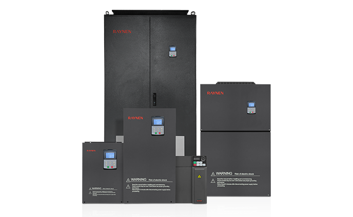
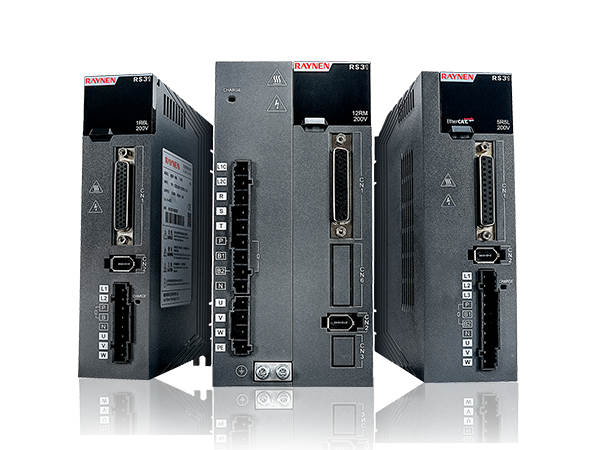
A medium-voltage variable frequency drive (MV VFD) — also referred to as a medium-voltage adjustable frequency drive (AFD), medium-voltage adjustable speed drive (ASD), or simply a medium-voltage drive — is a power electronics system that controls the speed and torque of a medium-voltage AC motor by varying the frequency and voltage of the electrical supply delivered to it. Where low-voltage VFDs operate at system voltages up to 690 V, medium-voltage drives cover the range from approximately 2.3 kV to 13.8 kV, addressing the large motor loads that are impractical to power through low-voltage systems due to the prohibitively high current levels that would result.
The physical reality that drives the need for medium-voltage equipment is straightforward: power equals voltage multiplied by current. A 2 MW motor load fed at 480 V draws over 2,400 amperes — cable sizes, switchgear ratings, and protective device requirements become unmanageable at this scale. The same 2 MW load fed at 4,160 V draws approximately 280 amperes — a level that is readily handled by standard medium-voltage switchgear and cabling. For industrial motors above 1 to 2 MW, medium-voltage supply is not a preference but a practical engineering necessity, and MV VFDs are the control technology that makes variable-speed operation of these large machines achievable.
Global installations of medium-voltage drives are concentrated in energy-intensive industries: oil and gas compression and pumping, mining conveyor and hoist drives, water and wastewater pumping stations, cement and aggregate processing, pulp and paper mills, steel rolling mills, and large HVAC systems. The economic case for MV VFDs rests primarily on the Affinity Laws governing centrifugal loads — pumps and fans — which state that shaft power varies with the cube of rotational speed. Reducing a pump's speed by just 20% reduces its power consumption by approximately 49%, producing energy savings that typically deliver full payback of the drive investment within 12 to 36 months in high-runtime applications.
How a Medium-Voltage VFD Works: The Basic Power Path
All medium-voltage drives, regardless of topology, share the same fundamental power conversion sequence. Understanding this sequence is the foundation for evaluating why different topologies make the engineering trade-offs they do.
The input supply — typically medium-voltage three-phase AC from the facility's distribution bus — enters the drive and is first converted to DC by a rectifier stage. This DC intermediate state decouples the grid-side converter from the motor-side converter, allowing the output frequency and voltage to be varied independently of the input supply frequency. An inverter stage then reconverts the DC into three-phase AC at the frequency and voltage required by the motor at any given operating point. The inverter switches — in most MV drive topologies, Insulated Gate Bipolar Transistors (IGBTs) — turn on and off thousands of times per second, controlled by Pulse Width Modulation (PWM) algorithms that shape the output waveform to approximate a sinusoidal voltage at the target frequency.
At medium voltage, the challenge is that individual power semiconductor switches cannot withstand the full system voltage across their terminals without failure. A single IGBT rated at 1,700 V cannot directly switch a 4,160 V bus. MV drive topologies address this constraint in several different ways — by stacking devices in series, using multilevel circuit configurations, or cascading multiple lower-voltage converter cells — and these different approaches produce the distinct topology families described below.
MV VFD Topologies: The Five Main Designs and Their Trade-Offs
There is no single dominant topology in the medium-voltage drive market. Each of the main designs represents a different engineering compromise between output waveform quality, harmonic performance, component ratings, motor compatibility, and system cost. Selecting the right topology for a given application is one of the most important engineering decisions in an MV drive project.
Three-Level Neutral Point Clamped (3-L NPC)
The three-level NPC topology has been commercially available since the late 1980s and remains one of the most widely deployed in the market. It uses a capacitor-split DC link with clamping diodes to produce three distinct voltage levels at the output, rather than the simple two-level (on/off) switching of a basic inverter. The three-level output produces significantly better output waveform quality than a two-level design, reducing dv/dt stress on the motor windings and lowering harmonic distortion. The NPC topology is available from ABB (ACS1000, ACS6080) and several other major manufacturers, typically at voltage ratings of 2.3 kV to 6.9 kV. Its key limitation is that the clamping diodes create an asymmetric load on the DC link capacitors during unbalanced operating conditions, requiring careful design management.
Cascaded H-Bridge (CHB) — Multi-Level Cell Technology
The cascaded H-bridge topology — also called multi-level cell technology or series-cell technology — builds the output waveform by cascading multiple low-voltage H-bridge inverter cells in series on each output phase. Each cell operates at conventional low-voltage levels (using proven 1,700 V rated IGBTs identical to those used in the high-volume LV drive industry), and the combined output of the series-connected cells produces the required medium-voltage output. With enough cells in series, the output waveform approaches a near-perfect sine wave, with extremely low harmonic distortion and very low dv/dt stress on motor insulation. The CHB topology is used by Benshaw (MVH2 Series), Siemens (SINAMICS GM150), and others. Its key advantages are inherent harmonic performance, compatibility with standard non-inverter-duty motors, and the modular cell replacement capability — a failed cell can be replaced individually without replacing the entire inverter assembly, minimizing downtime. It also requires a multi-winding input transformer to provide isolated power supplies for each cell bank.
Modular Multilevel Converter (MMC)
The modular multilevel converter is a newer topology that extends the multilevel concept further, using large numbers of identical half-bridge or full-bridge sub-modules connected in series to form each arm of the converter. MMC drives produce extremely high-quality output waveforms with very low harmonic content and are scalable to very high power levels. The topology is gaining commercial traction in applications above 10 MW and is used in ABB's ACS6080 and similar high-power platforms. Its complexity and the large number of capacitor-based sub-modules require sophisticated control algorithms and more extensive monitoring systems than simpler topologies, which has historically limited its use to the largest and highest-value applications.
PWM Current Source Inverter (CSI)
Current source inverter drives use a large DC inductor rather than a capacitor bank as the DC link energy storage element, giving the inverter the character of a current source rather than a voltage source. CSI drives produce a current-controlled output waveform and are particularly well suited to synchronous motor drives and applications requiring regenerative braking, since the inductor-based DC link handles bidirectional energy flow more naturally than a capacitor-based VSI. The output waveform quality from a PWM CSI is good but typically requires a capacitor filter at the motor terminals to mitigate high-frequency content. Rockwell Automation's PowerFlex 7000 is one of the most widely recognized CSI-based MV drives in service.
Load-Commutated Inverter (LCI)
The load-commutated inverter is a mature technology used for very high-power, large synchronous motor drives — compressors, pumps, and fans above 10 to 20 MW in ratings. LCI drives use thyristors (SCRs) rather than IGBTs as switching devices; thyristors are commutated off by the back-EMF of the synchronous motor rather than by gate-turn-off circuitry, which is why the load (the motor) must be a synchronous machine operating above a minimum speed to provide the commutation voltage. LCI drives are extremely robust and have very high power capability, but they produce relatively high harmonic content and are limited to synchronous motor loads at high power levels. They are the workhorse technology for large LNG compressor trains, pipeline pumping stations, and large industrial fans.
| Topology | Switching Devices | Output Quality | Motor Compatibility | Best For |
|---|---|---|---|---|
| 3-Level NPC | IGBT | Good | Standard MV motors | General industrial, 2.3–6.9 kV |
| Cascaded H-Bridge (CHB) | Low-voltage IGBT cells | Excellent (near-sine wave) | Standard non-inverter-duty motors | Retrofit, pumps, fans, compressors |
| Modular Multilevel (MMC) | IGBT sub-modules | Excellent | Standard MV motors | High power (10 MW+), scalable applications |
| PWM Current Source (CSI) | SGCT / IGCT | Good (with filter) | Induction and synchronous motors | Regenerative loads, synchronous motors |
| Load-Commutated Inverter (LCI) | Thyristor (SCR) | Moderate (high harmonics) | Synchronous motors only | Very high power (10–100 MW+), compressors |
Energy Savings: The Core Business Case for MV VFDs
The primary economic driver for most MV VFD installations is energy cost reduction on centrifugal pump and fan loads. The Affinity Laws — the fundamental fluid dynamics relationships governing centrifugal machines — state that flow varies linearly with shaft speed, pressure varies with the square of speed, and power varies with the cube of speed. This cubic relationship makes speed control disproportionately powerful as an energy management strategy.
In a process that operates a pump at 80% of full speed for a significant portion of its runtime, the drive is consuming approximately 51% of the power that would be drawn at full speed — a reduction of nearly half from a 20% speed reduction. For a 2 MW pump motor running at reduced speed for 6,000 hours per year at an industrial electricity rate, the annual energy saving can exceed hundreds of thousands of dollars. Against a total installed MV VFD cost that typically ranges from $150 to $500 per kW of motor rating depending on voltage class and topology, payback periods of one to three years are achievable for high-runtime centrifugal applications.
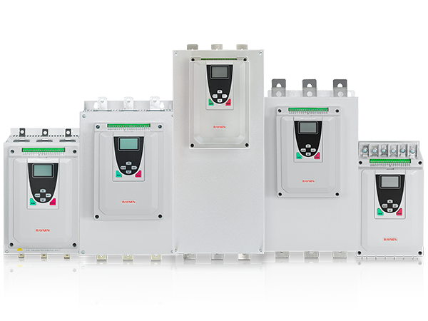
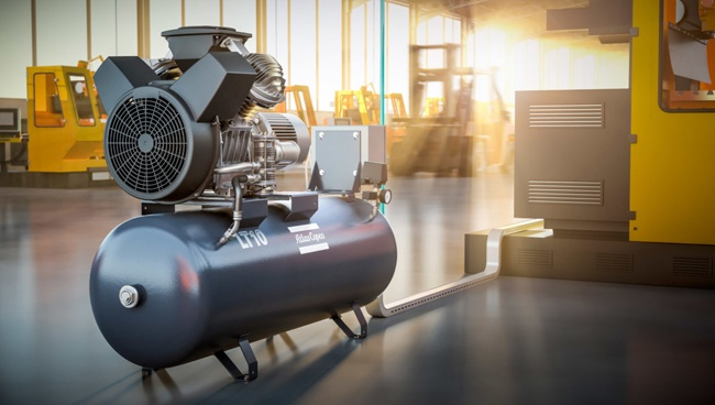
Beyond centrifugal load savings, MV VFDs deliver additional energy and operational benefits. Soft starting — accelerating the motor gradually from zero speed rather than applying full voltage across the line — eliminates the high inrush current (typically 6 to 8 times full-load current) that occurs during across-the-line starting. This eliminates mechanical shock on the drive train, reduces thermal stress on the motor windings, and prevents the voltage sag on the distribution bus that accompanies large motor starts. Precise speed control also enables process optimization that can reduce material waste, improve product quality, and reduce wear on downstream mechanical equipment — benefits that add to the financial case beyond the electricity cost reduction alone.
Harmonics: What MV VFDs Generate and How to Manage Them
Variable frequency drives, including medium-voltage types, are non-linear loads — they draw current from the supply in pulses rather than smoothly, generating harmonic currents that flow into the power system. These harmonic currents cause voltage distortion on the distribution bus, which can interfere with sensitive instrumentation, overheat transformers and cables designed for fundamental frequency operation, and cause nuisance tripping of protective devices. Managing harmonic distortion is a required element of any MV VFD installation, not an optional refinement.
How Different Topologies Affect Harmonic Performance
The most important differentiator in harmonic performance is the drive topology's rectifier design and pulse number. A standard six-pulse rectifier — the simplest and most common design — generates 5th, 7th, 11th, and 13th harmonic currents as its dominant components. Twelve-pulse and eighteen-pulse rectifier configurations cancel lower-order harmonic pairs, reducing Total Harmonic Distortion (THD) significantly. The cascaded H-bridge topology, by virtue of its multi-winding input transformer which provides phase-shifted supply to each cell bank, inherently achieves effective pulse numbers of 18 to 36 or higher depending on the number of cells, producing very low input harmonic distortion without additional filtering hardware. The IEEE 519 standard, which is the benchmark harmonic specification for industrial power systems in North America, sets limits on both current THD at the point of common coupling and on individual harmonic voltage distortion — most MV VFD procurement specifications require compliance with IEEE 519 as a minimum condition of supply.
Harmonic Mitigation Strategies
When the inherent harmonic performance of the selected drive topology does not meet the project's power quality requirements, additional mitigation hardware is available. Passive harmonic filters — tuned LC circuits installed on the drive's input bus — absorb specific harmonic frequencies before they enter the distribution system. Active front-end (AFE) rectifier stages use PWM-controlled switching on the input side of the drive to draw a nearly sinusoidal input current, achieving very low THD without the resonance risks associated with passive filters. Input line reactors provide partial harmonic attenuation at lower cost than full harmonic filters but do not achieve IEEE 519 compliance on their own for most installations. The harmonic mitigation strategy must be determined during the engineering phase of the project — not as an afterthought — because it affects the transformer rating, the drive input panel design, and the overall system cost.
Motor and Cable Compatibility Considerations
Not all motors and cable configurations are equally compatible with MV VFD operation. The output voltage waveform from a drive — even a high-quality multilevel design — is not a pure sine wave, and the high-frequency switching components in the output can cause problems that do not occur in across-the-line motor operation.
Motor Insulation Stress and Reflected Waves
Early MV drive designs — particularly simple two-level switching topologies — produced steep-fronted voltage pulses at the motor terminals that caused rapid insulation degradation and premature motor failures. This led to the requirement for "inverter duty" motors with reinforced insulation systems in low-voltage VFD applications. One of the key advantages of multilevel MV drive topologies — particularly CHB and NPC designs — is that their higher output waveform quality dramatically reduces the dv/dt (rate of voltage rise) and peak voltage stress at the motor terminals, making them compatible with standard medium-voltage motors that have not been specifically rated for drive operation. However, cable length between the drive and motor remains an important variable: long motor cables act as transmission lines and can produce voltage reflections that nearly double the peak voltage at the motor terminals. For installations with long cable runs, a dv/dt filter or sine filter at the drive output is a standard protective measure.
Motor Bearing Currents
PWM switching in VFDs generates common-mode voltages — voltages that appear simultaneously across all three output phases with respect to ground — that can cause current to flow through the motor shaft bearings to ground. These bearing currents erode the bearing raceway surface through electrical discharge machining (EDM), creating pitting that produces noise and eventually bearing failure. Shaft grounding rings, insulated bearings, and common-mode filters are the standard mitigation measures. For large medium-voltage motors, the risk is well understood and protective measures are routinely incorporated into the drive or motor specification — but they must be explicitly addressed rather than assumed to be unnecessary.
Industry Applications Where MV VFDs Deliver the Most Value
Medium-voltage variable frequency drives are deployed across a wide range of industries, but certain application categories deliver the highest return on investment because they combine large motor ratings, high annual runtime, and significant process variability that makes speed control valuable.
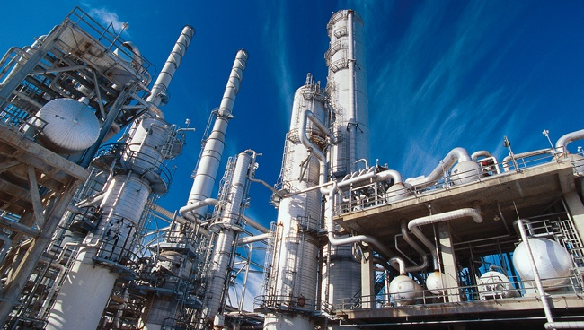
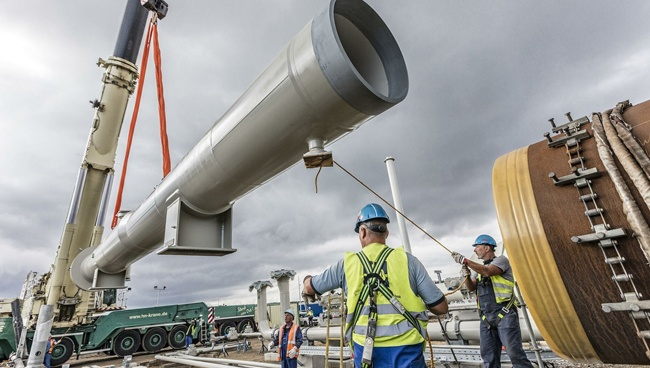
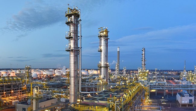
- Oil and gas: Pipeline pumps, compressor trains for gas transmission and LNG liquefaction, offshore platform seawater lift pumps, and injection water pumps all represent large medium-voltage motor loads where both energy savings and soft-start capability justify MV VFD installation. In offshore environments, the compact footprint and arc flash protection of modern enclosed MV drives address the space and safety constraints of platform installations.
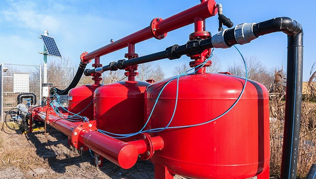
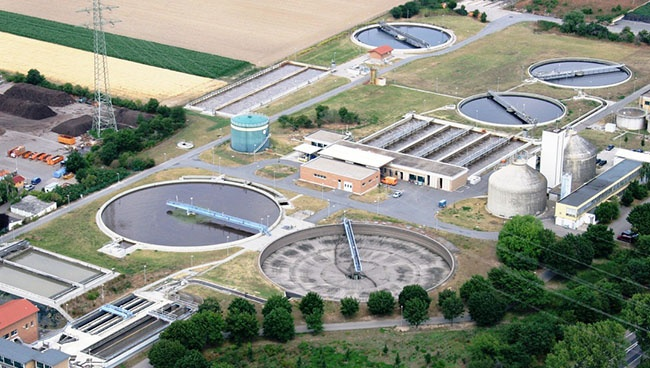
- Water and wastewater: Large municipal pumping stations — intake pumps, transmission mains booster pumps, and wastewater lift stations — are among the most common MV VFD applications globally because the combination of large motor ratings, continuous duty cycles, and variable demand profiles produces fast energy payback. MV drives in wastewater applications are increasingly specified with IP54 or higher enclosures and with environmental sealing against hydrogen sulfide and moisture.
- Mining: Conveyor belt drives, hoist and winder drives, large ventilation fans, and mill drives (SAG mills, ball mills) represent the major MV VFD applications in mining. The ability to control conveyor acceleration precisely reduces mechanical stress on the belt and reduces maintenance intervals on belt splices and tail pulleys — an operational benefit that adds to the energy cost case in high-tonnage operations.
- Cement and aggregate: Kiln drives, raw mill drives, and large fan systems in cement plants operate continuously and represent significant electrical loads. The variable torque requirements of these processes — particularly kiln starting, which requires high torque at very low speed — make VFD control superior to across-the-line or soft-starter alternatives for both performance and equipment protection.
- Power generation: Boiler feed pumps, forced draft fans, induced draft fans, and circulating water pumps in thermal power stations are classic high-runtime, variable-load applications where MV VFD retrofits have produced energy savings of 20 to 40% on previously throttle-controlled or damper-controlled systems.
- Marine and offshore: Electric propulsion systems for vessels — thrusters, podded drives, and main propulsion drives — use medium-voltage drives to control large propulsion motors. Cruise ships, LNG carriers, offshore support vessels, and naval applications represent a growing market for MV VFDs designed to meet marine classification society requirements (DNV, Lloyd's Register, ABS).
Installation and Commissioning: What a Successful MV VFD Project Requires
A medium-voltage variable frequency drive is not a plug-and-play device. The mechanical, electrical, and systems integration work required to install and commission an MV drive represents a substantial portion of the total project cost and is where most project problems originate when not properly planned. Understanding what a correct installation requires prevents the common mistakes that produce delayed commissioning, performance shortfalls, and early equipment problems.
Civil and Mechanical Requirements
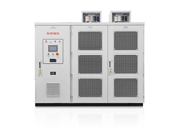
MV VFD enclosures are large and heavy — a typical 2 MW CHB drive with its input transformer may weigh 5,000 to 15,000 kg or more and require a dedicated electrical room with reinforced flooring, controlled temperature and humidity, and forced ventilation or air conditioning to maintain the drive's specified operating environment. Most manufacturers specify a maximum ambient temperature of 40°C and a maximum relative humidity of 95% non-condensing. The input transformer, if separate from the drive enclosure, requires its own space allocation and fire separation per local electrical codes. Access doors must be sized for the largest replaceable assembly — typically a complete power cell or transformer winding — to allow maintenance without major disassembly of adjacent equipment.
Cable Design and Routing
Medium-voltage cable between the source transformer and the drive input, and between the drive output and the motor, must be specified for the system voltage class, the continuous current rating, the installation conditions (conduit, tray, direct burial), and the length of the run. As noted above, long motor cable runs can cause reflected wave voltage amplification at the motor terminals — most manufacturers specify maximum cable lengths for operation without output filters, and these limits must be verified against the actual cable run in the project layout before finalizing the drive selection. All MV cabling requires cable shielding, proper termination, and grounding practices in accordance with the applicable electrical code and the manufacturer's installation requirements.
Control System Integration
MV drives are invariably integrated into plant control systems through digital communications — Modbus RTU, Profibus, Profinet, EtherNet/IP, DeviceNet, and other industrial protocols are supported by modern drive platforms. The control system integration must be designed before the drive is commissioned, including definition of all speed reference sources, all drive enable and fault signals, all process feedback variables (speed, current, power, fault codes) that will be monitored by the plant DCS or SCADA system, and all protective interlocks that must trip the drive from the process safety system. Commissioning without a fully tested and documented control system interface is one of the most common causes of delayed drive startup on large projects.
Commissioning Procedure
MV drive commissioning must be performed by qualified engineers with specific training on the drive platform and with appropriate personal protective equipment and safe work procedures for medium-voltage electrical work. The commissioning sequence includes pre-energization insulation resistance testing of all cables and the motor, verification of control wiring continuity and polarity, confirmation of correct phase rotation at the drive input and output, parameter programming to match the motor nameplate data and the application's speed, torque, and protection requirements, no-load rotation check at low speed before connecting the load, and load test through the full speed range with verification of speed regulation, current limits, and protective function operation. Factory acceptance testing (FAT) of the drive at the manufacturer's facility before shipment is standard practice for large MV drive projects and provides an opportunity to verify the complete parameter set and control system interface before the equipment reaches site.
Key Specifications to Confirm Before Purchasing a Medium-Voltage VFD
Medium-voltage drives represent capital investments ranging from several hundred thousand to several million dollars depending on power rating, topology, and accessories. Getting the specification right before purchasing protects the investment and ensures the drive performs as required over its operating life. The following specifications should be confirmed in writing before a purchase order is issued.
- Input voltage rating and tolerance: Confirm the drive's rated input voltage matches the facility's supply voltage (2.3 kV, 3.3 kV, 4.16 kV, 6.0 kV, 6.6 kV, 11 kV, or 13.8 kV are the standard levels) and confirm the input voltage tolerance — typically ±10% of nominal — is compatible with the actual voltage variation on the facility's distribution bus.
- Motor power and current rating: The drive must be rated for the motor's full-load current at the motor terminal voltage. Confirm both the continuous current rating and the overload rating — typically 110% or 150% for a defined short-duration period — against the motor's known load profile including starting, peak load, and regenerative conditions.
- Output harmonic distortion and IEEE 519 compliance: Specify the maximum permissible current THD at the point of common coupling with the facility distribution system and confirm that the drive system — including any harmonic mitigation equipment — achieves this limit under the expected operating conditions. Request sample input current waveform data from previous installations with similar configurations.
- Motor cable length compatibility: Provide the actual motor cable length in the project and confirm the manufacturer's maximum cable length without output filters at the proposed operating voltage and cable type. If the run exceeds the limit, specify the required output filter type and obtain confirmation of the combined drive and filter system's voltage at the motor terminals.
- Enclosure rating and environmental specifications: Confirm the enclosure IP or NEMA rating against the installation environment. Indoor clean room environments may accept NEMA 1 (IP20); industrial environments with dust, moisture, or corrosive atmosphere require NEMA 12 (IP54) or higher. Wastewater, mining, and offshore environments typically require additional environmental protection beyond standard NEMA ratings.
- Bypass and redundancy provisions: For critical processes where motor downtime is unacceptable, specify the bypass arrangement — whether a full across-the-line bypass contactor is required, whether synchronous transfer capability (transferring between VFD output and line power without stopping the motor) is needed, and whether power cell bypass (specific to CHB topology) provides adequate redundancy for reduced-speed operation following a cell failure.
- Arc flash protection: MV drives contain stored energy in DC link capacitors and are fed from medium-voltage bus — the arc flash incident energy in the event of an internal fault is potentially very high. Specify arc-resistant enclosure construction (tested to IEEE C37.20.7 or equivalent) for installations where personnel access during normal operations creates exposure risk. Some manufacturers offer arc-resistant MV drive designs — such as Eaton's SC9000 EP — specifically targeting wastewater, mining, and oil and gas environments.
- Certifications and standards compliance: Confirm compliance with the applicable standards for the installation location and industry: IEEE 519 for harmonics, UL 508A or equivalent for panel construction, IEC 61800 series for adjustable speed drive systems, and any industry-specific standards (API 541/547 for oil and gas motors, marine classification society requirements for offshore/marine). ISO 9001 certification of the manufacturing facility should be a baseline requirement for all MV drive procurement.
- Manufacturer service network and spare parts availability: Confirm that the manufacturer has qualified service engineers available within a commercially acceptable response time for your facility's location. Identify the critical spare parts — power cells, gate drive boards, control processors — and confirm they are available from stock or with an acceptable lead time. For remote or international locations, a local spare parts holding agreement with the manufacturer or a qualified service partner reduces the risk of extended downtime following a component failure.
Previous Post
AC Servo Motor Explained: How It Works, Types, and How to Choose the Right One
Next Post
Low-Voltage Variable Frequency Drive: Everything You Need to Know Before You Buy or Install One
Copyright 2024 Fujian Raynen Technology Co.,Ltd. All Rights Reserved.
Privacy Policy  Motor Control Manufacturers