English
 Español
 عربى
عربى


1.Introduction to AC Drives (Variable Frequency Drives) In the realm of modern industrial control an......
READ MOREHome / News / Industry News / Programmable Logic Controller Explained: What It Is, How It Works, and How to Choose One
Programmable Logic Controller Explained: What It Is, How It Works, and How to Choose One
Content
- 1 What a Programmable Logic Controller Is and Why It Matters in Industrial Automation
- 2 PLC Hardware Architecture: What's Inside the Controller
- 3 How a PLC Executes Its Program: The Scan Cycle Explained
- 4 PLC Programming Languages: The Five Standard Options and When to Use Each
- 5 Types of PLCs: Compact, Modular, and Rack-Based Systems
- 6 PLC vs. DCS vs. PAC: Understanding the Differences
- 7 Key Specifications to Evaluate When Selecting a PLC
- 8 Common PLC Applications Across Industries
- 9 PLC Troubleshooting Fundamentals: How to Diagnose Faults Systematically
What a Programmable Logic Controller Is and Why It Matters in Industrial Automation
A programmable logic controller (PLC) is a ruggedized digital computer purpose-built for controlling industrial machinery and automated processes. Unlike a general-purpose computer, a PLC is designed from the ground up to survive the physical demands of factory floors — wide temperature ranges, electrical noise, vibration, dust, and humidity — while executing control logic continuously and reliably, often for years without interruption. The defining characteristic of a PLC is its ability to monitor real-world inputs from sensors and switches, execute a user-written control program, and drive real-world outputs — motors, valves, indicators, and actuators — based on the results of that logic.
Before PLCs existed, industrial control systems were built from banks of electromechanical relays wired together to form logic circuits. Changing the control behavior of a machine meant physically rewiring the relay panel — a time-consuming, error-prone process that required skilled technicians and significant downtime. When the first commercially successful PLC was introduced by Modicon in 1969, developed by engineer Dick Morley in response to a request from General Motors to replace relay logic in automotive assembly lines, it solved this problem by replacing hardwired relay circuits with programmable software logic. The control behavior of a machine could now be changed by modifying a program rather than rewiring hardware, transforming both the speed and economics of industrial automation.
Today, PLCs are the backbone of automated control across manufacturing, energy, water treatment, transportation, building automation, and dozens of other industries. Understanding how they work, how they are programmed, and how to select the right one for a specific application is fundamental knowledge for anyone involved in industrial engineering, systems integration, or operations technology.
PLC Hardware Architecture: What's Inside the Controller
A programmable logic controller is not a single monolithic device — it is a system of hardware components that work together. Understanding the function of each component explains both the PLC's capabilities and its limitations, and informs decisions about configuration and expansion when designing a control system.
Central Processing Unit (CPU)
The CPU is the computational core of the PLC. It executes the user program, manages memory, handles communication with I/O modules and external devices, and performs system diagnostics. PLC CPUs are not the same as general-purpose microprocessors — they are optimized for deterministic real-time execution, meaning the CPU must complete each scan cycle within a guaranteed maximum time regardless of what else is happening in the system. Scan cycle times for modern PLCs typically range from 0.1 ms to 10 ms depending on program complexity and CPU speed. Some high-performance PLCs used in motion control or high-speed packaging achieve sub-millisecond scan times. CPU memory is divided into program memory (where the user logic is stored), data memory (where variable values are held during execution), and system memory (used by the operating system for internal functions).
Input and Output Modules
I/O modules are the interface between the PLC and the physical world. Input modules receive signals from field devices — limit switches, pushbuttons, proximity sensors, thermocouples, pressure transmitters, and encoders — and convert them into digital values the CPU can read. Output modules receive commands from the CPU and convert them into signals that drive field devices — motor starters, solenoid valves, indicator lamps, and servo drives. I/O is categorized as discrete or analog: discrete (digital) I/O handles binary on/off signals, while analog I/O handles continuously variable signals such as 4–20 mA current loops or 0–10V voltage signals representing temperature, pressure, or flow values. Most PLCs also offer specialty I/O modules for specific functions — high-speed counter modules for encoder pulse counting, thermocouple modules with built-in cold junction compensation, and communication modules for fieldbus protocols.
Power Supply
The PLC power supply converts incoming AC or DC line voltage — typically 120V AC, 240V AC, or 24V DC — into the regulated low-voltage DC power required by the CPU and I/O modules. Most PLC backplanes and racks use 5V DC or 3.3V DC internally for logic components and 24V DC for field-side I/O circuits. The power supply's current capacity must be matched to the total power draw of all installed modules — undersizing the power supply is a common configuration error in large systems with many I/O modules. Redundant power supply configurations are available for applications where power supply failure would have unacceptable consequences.
Communication Interfaces
Modern PLCs include multiple communication interfaces for connecting to programming tools, human-machine interfaces (HMIs), supervisory control and data acquisition systems (SCADA), other PLCs, and field devices. Common communication ports and protocols include Ethernet/IP, PROFINET, Modbus TCP, PROFIBUS, DeviceNet, CANopen, and RS-232/RS-485 serial ports. The availability of industrial Ethernet protocols has transformed PLC system architecture over the past two decades, enabling seamless integration of control, monitoring, and enterprise data systems across a single network infrastructure rather than separate proprietary networks for each function.
How a PLC Executes Its Program: The Scan Cycle Explained
The operating behavior of a PLC is fundamentally different from a conventional computer program that runs once from start to finish. A PLC executes its control program in a continuous repeating loop called the scan cycle. Understanding the scan cycle is essential for writing correct PLC programs and for diagnosing timing-related control problems.
Each scan cycle consists of four sequential phases that execute in order, every cycle:
- Input scan: The CPU reads the current state of all physical input signals and copies these values into a dedicated memory area called the input image table. During program execution, the program reads input states from this image table rather than directly from the physical inputs — ensuring that input values remain consistent throughout a single scan even if a physical input changes state mid-cycle.
- Program execution: The CPU executes the user program from the first instruction to the last, evaluating logic conditions and computing output values. Results are written to an output image table in memory rather than immediately to physical outputs.
- Output scan: The CPU copies the values from the output image table to the physical output modules, which update their output signals accordingly. This is the point at which the results of the program execution are physically applied to the controlled equipment.
- Housekeeping: The CPU performs internal diagnostic checks, updates communication buffers, services communication requests from HMIs and programming tools, and prepares for the next scan cycle.
The total time to complete one full scan cycle is the scan time. For most industrial applications, a scan time of 5 to 20 ms is acceptable. Applications requiring faster response — detecting high-speed machine events, controlling servo axes, or monitoring safety-critical inputs — may require interrupt-driven processing, where specific inputs trigger immediate program execution outside the normal scan cycle, or dedicated high-speed CPUs with sub-millisecond scan performance.
PLC Programming Languages: The Five Standard Options and When to Use Each
PLC programming languages are standardized by the IEC 61131-3 international standard, which defines five languages that compliant PLCs must support. In practice, most manufacturers implement all five, though some have traditionally favored particular languages for specific applications. Choosing the right language for a given task improves code readability, maintenance ease, and debugging efficiency.
Ladder Diagram (LD)
Ladder Diagram is the most widely used PLC programming language globally and is the direct graphical descendant of relay logic diagrams. Programs are represented as a series of horizontal rungs between two vertical power rails — exactly like a ladder. Each rung contains contacts (representing input conditions) and coils (representing outputs), connected in series or parallel to express logic relationships. An engineer familiar with relay wiring diagrams can read and understand ladder logic with minimal additional training, which is why it remains dominant in discrete manufacturing, machine control, and any industry with a large installed base of relay-logic technicians. Ladder Diagram is best suited for discrete control applications involving sequences of on/off operations, interlocks, and timing logic.
Function Block Diagram (FBD)
Function Block Diagram represents control logic as a network of interconnected graphical function blocks, where signals flow from left to right through blocks that perform defined operations — logic gates, timers, PID controllers, arithmetic functions, and communication blocks. FBD is particularly well suited to process control applications involving continuous analog signals, PID control loops, and complex signal processing chains, where the flow of data between functional elements is more intuitive to represent graphically than as sequential ladder rungs. FBD is the preferred language in chemical processing, oil and gas, and power generation applications.
Structured Text (ST)
Structured Text is a high-level textual language with syntax resembling Pascal or C. It supports variables, data types, expressions, conditional statements (IF-THEN-ELSE), loops (FOR, WHILE, REPEAT), and function calls — making it the most powerful of the IEC 61131-3 languages for complex algorithms and mathematical computations. ST is ideal for implementing complex recipe management, data calculations, string manipulation, and custom function blocks that would be impractical to express in graphical languages. Its adoption has increased substantially as PLCs have taken on more complex computational tasks previously handled by separate industrial computers.
Sequential Function Chart (SFC)
Sequential Function Chart provides a high-level graphical representation of a process as a sequence of steps connected by transitions. Each step contains the actions to be performed when that step is active; each transition defines the condition that must be satisfied to advance to the next step. SFC is excellent for programming machines that operate through defined sequential phases — filling a tank, executing a wash cycle, running a batch process — because the step-by-step structure of the program directly mirrors the physical sequence of the machine operation, making it easy to understand, debug, and modify. SFC programs for individual steps and transitions can be written in any of the other four IEC languages.

Instruction List (IL)
Instruction List is a low-level textual language resembling assembly language, where each line contains a single instruction operating on an accumulator register. It was included in IEC 61131-3 to provide a language familiar to programmers from the early days of PLC development. IL is rarely used in new projects today — most modern PLC programming environments have deprecated it in favor of Structured Text — but it remains in the standard for backward compatibility with legacy programs written in IL on older controllers.
| Language | Type | Best For | Typical Industry |
|---|---|---|---|
| Ladder Diagram (LD) | Graphical | Discrete logic, interlocks, sequences | Manufacturing, machine control |
| Function Block Diagram (FBD) | Graphical | Analog control, PID loops, signal flow | Process industry, oil and gas |
| Structured Text (ST) | Textual | Complex algorithms, math, data handling | All industries, advanced applications |
| Sequential Function Chart (SFC) | Graphical | Batch sequences, step-based machines | Food, pharma, batch processing |
| Instruction List (IL) | Textual | Legacy programs, low-level optimization | Legacy systems (deprecated in new work) |
Types of PLCs: Compact, Modular, and Rack-Based Systems
PLCs are available in form factors ranging from palm-sized micro controllers to multi-rack systems filling entire control cabinets. Selecting the right form factor involves matching the controller's I/O capacity, expansion capability, processing power, and physical size to the application requirements and budget.
Compact (Nano and Micro) PLCs
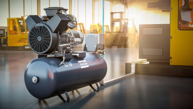
Compact PLCs integrate the CPU, power supply, and a fixed number of I/O points into a single housing. They are the most cost-effective option for small applications with a defined, limited I/O count — typically 8 to 64 I/O points. Some compact PLCs offer limited expansion through add-on modules, but expansion capacity is much more constrained than modular systems. Common applications include small machine control, conveyor sections, pump stations, and building automation sub-systems. Siemens S7-1200, Allen-Bradley Micro820, and Mitsubishi FX5U are representative examples of this category. Compact PLCs are not appropriate when the I/O count or communication requirements of the application are likely to grow significantly over the system's lifetime.
Modular PLCs
Modular PLCs separate the CPU, power supply, and I/O into individual modules that mount on a common backplane or DIN rail and connect via an internal bus. This architecture allows the system to be configured precisely for the application — adding exactly the types and quantities of I/O modules needed — and expanded later by adding modules to unused backplane slots or additional backplanes. Modular systems scale from small configurations of a CPU plus a handful of I/O modules up to large systems with hundreds of I/O points distributed across multiple racks. Siemens S7-300/S7-1500, Allen-Bradley ControlLogix, and Omron NX/NJ series are leading modular PLC platforms used across demanding industrial applications worldwide.
Rack-Based and Large-Scale PLCs
Large-scale rack-based PLCs support very high I/O point counts — from several hundred to tens of thousands of I/O points across distributed I/O racks — and are used in continuous process plants, power generation facilities, and large-scale manufacturing lines. These systems commonly feature redundant CPU configurations where a standby CPU takes over automatically if the primary fails, redundant power supplies, and redundant communication networks — providing the high availability required in applications where unplanned shutdown has severe operational or safety consequences. The Siemens S7-400H, Allen-Bradley ControlLogix with redundancy, and Yokogawa STARDOM are examples of platforms designed for this level of criticality.
PLC vs. DCS vs. PAC: Understanding the Differences
Three controller types dominate industrial automation: PLCs, Distributed Control Systems (DCS), and Programmable Automation Controllers (PACs). The boundaries between them have blurred considerably as all three have adopted modern networking, high-level programming, and advanced processing capabilities — but meaningful differences in design philosophy, application fit, and total cost of ownership remain.
A PLC originated in discrete manufacturing and is optimized for fast scan-cycle execution of sequential and combinational logic. It excels in machine control, packaging lines, and discrete manufacturing where deterministic response to binary events is the primary requirement. PLC systems are typically less expensive per I/O point than DCS systems and are supported by a large base of trained technicians in manufacturing environments.
A DCS (Distributed Control System) was developed for continuous process industries — oil refining, chemical production, power generation — where the primary requirement is regulatory control of continuous analog variables across a large number of I/O points. DCS platforms are built around a unified engineering environment where configuration, display, historian, and control functions are tightly integrated by the same vendor. This integration reduces engineering time for large systems but creates significant vendor dependency and higher platform costs.
A PAC (Programmable Automation Controller) is a term used to describe modern high-performance controllers that combine PLC-style discrete control with the analog process control, motion control, and networking capabilities historically associated with DCS platforms — all in a single controller and programming environment. National Instruments CompactRIO and Opto 22 EPIC are examples. PACs are particularly well suited to applications that cross the traditional PLC/DCS boundary, such as hybrid batch processes that combine sequential operations with continuous control loops.
Key Specifications to Evaluate When Selecting a PLC
Selecting a PLC platform for a new application or a retrofit project involves evaluating a set of technical and practical parameters that collectively determine whether the chosen system will meet current requirements and remain supportable over the system's expected lifetime — typically 15 to 25 years in industrial settings.
- I/O count and type: Determine the total number of discrete input, discrete output, analog input, and analog output points required, add a growth margin of at least 20%, and confirm the chosen platform supports the required I/O types in suitable modules. Special I/O types — high-speed counters, thermocouple inputs, encoder interfaces, serial communication modules — must be verified specifically.
- CPU performance and memory: For applications with large programs, many analog PID loops, or fast response requirements, compare CPU scan times under typical program load. Program memory requirements are difficult to estimate precisely at the specification stage — as a rule of thumb, specify at least twice the memory estimated to be required by the initial program to accommodate future modifications and additions.
- Communication protocols: Confirm the PLC natively supports the communication protocols required to interface with HMIs, SCADA systems, drives, robots, and any third-party devices specified in the system architecture. Native protocol support is always preferable to protocol conversion gateways, which add cost, latency, and points of potential failure.
- Environmental ratings: Verify the CPU and I/O modules carry appropriate ratings for the installation environment — operating temperature range, humidity tolerance, vibration and shock resistance, and protection against corrosive atmospheres if the installation is in a chemical or marine environment.
- Safety certification requirements: Applications involving personnel safety — emergency stop circuits, safety interlocks, light curtains — may require a Safety PLC (also called a Safety Instrumented System controller) certified to IEC 62061 or ISO 13849. Standard PLCs cannot be used to implement safety functions without additional certified safety relays or safety I/O modules, regardless of how the logic is written.
- Vendor support and spare parts availability: The installed platform must remain supported with firmware updates, spare hardware, and technical support for the expected system life. Selecting a platform from a vendor with a strong regional support presence and a documented product lifecycle commitment significantly reduces the risk of being stranded with an unsupported system mid-life.
- Programming software licensing and cost: PLC programming environments are proprietary — each manufacturer's controllers require their specific software. Confirm the licensing model (perpetual, annual subscription, per-seat), the cost of multiple programmer licenses, and whether the software runs on current operating systems without requiring legacy Windows versions.
Common PLC Applications Across Industries
Programmable logic controllers appear in almost every industry that uses any form of automated or semi-automated process. The diversity of PLC applications reflects the technology's fundamental versatility — the same core architecture that controls a bottling line also manages a water treatment plant or coordinates a building's HVAC and access control systems.
Discrete Manufacturing and Assembly
Automotive assembly, electronics manufacturing, metal fabrication, and consumer goods production all rely heavily on PLCs to sequence robot actions, control conveyor speeds, manage part detection and rejection, and coordinate safety interlocks across multi-machine production cells. A single automotive body assembly line may contain hundreds of individual PLCs coordinating welding robots, transfer systems, quality inspection stations, and material handling equipment, all networked to a supervisory SCADA system that monitors production rates and fault conditions in real time.
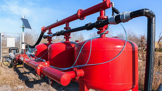
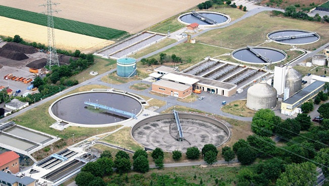
Water and Wastewater Treatment
Municipal water treatment and distribution facilities use PLCs to control pumping stations, chemical dosing systems, filtration processes, and reservoir level management. Remote pumping stations miles from the main treatment plant are commonly controlled by standalone PLCs communicating with the central SCADA system over cellular or radio links. PLCs in water applications must handle a mix of discrete control (valve open/close sequencing) and analog regulation (flow rate, chemical dose rate, pressure control) reliably and without requiring on-site operators at each remote location.
Food and Beverage Processing
Food processing environments impose specific requirements on PLC hardware — stainless steel enclosures or sealed plastic housings rated for washdown environments, and I/O modules tolerant of the temperature extremes of freezer-to-cookroom transitions. PLCs in food plants control mixing and blending sequences, pasteurization temperature profiles, filling and sealing machines, and clean-in-place (CIP) wash cycles. Regulatory requirements for food safety documentation mean PLC systems in this sector often include electronic batch record generation, automatically logging process parameters for each production batch to demonstrate compliance with HACCP and food safety standards.
Building Automation and Infrastructure
Large commercial and industrial buildings use PLCs and dedicated building automation controllers — which are essentially specialized PLCs — to manage HVAC systems, lighting control, access control, elevator dispatch, and energy management. Tunnel ventilation, airport baggage handling, and stadium infrastructure control are further examples of large-scale building-related applications where PLC systems coordinate hundreds of distributed field devices across sprawling physical facilities. The convergence of building automation and industrial automation protocols — particularly as both sectors adopt Ethernet-based communication — is making general-purpose PLCs increasingly competitive with traditional building automation system controllers in this market.
PLC Troubleshooting Fundamentals: How to Diagnose Faults Systematically
Effective PLC troubleshooting follows a systematic process of elimination that narrows the fault location from the system level down to the specific component or program element responsible. A structured approach reduces diagnostic time and avoids the random replacement of expensive components that are not actually faulty.
- Check the CPU status indicators first. PLC CPUs provide LED indicators showing run/stop status, fault conditions, and communication activity. A solid red fault light indicates a hardware or program fault — connect the programming software and read the diagnostic buffer, which logs the fault code, time stamp, and often the specific program element that caused the fault.
- Use the programming software's online monitoring capability. Most PLC programming environments allow the programmer to connect to a running controller and view the live state of all inputs, outputs, and internal variables while the program executes. This online monitoring capability makes it straightforward to observe whether an input is reading correctly, whether a logic condition is evaluating as expected, and whether an output is being commanded but not responding — distinguishing between program logic errors and hardware I/O failures.
- Distinguish between hardware faults and program logic errors. If an output module's status LED shows the output is commanded on by the PLC but the field device is not operating, the problem is external to the PLC — wiring, fuse, field device, or power supply. If the output module LED shows the output is not being commanded, the problem is in the program logic or the input conditions driving it.
- Check power supply voltages under load. Many intermittent PLC faults that appear to be CPU or I/O problems are actually caused by a power supply that is marginal — providing correct voltage under light load but sagging below specification under full I/O load. Measure supply rail voltages at the backplane connector with all modules installed and active.
- Inspect for environmental causes. Intermittent faults that correlate with time of day, weather conditions, or nearby equipment operation often point to environmental factors — condensation forming inside enclosures during temperature cycling, vibration loosening terminal block connections, or electrical noise from variable frequency drives or welding equipment coupling into I/O wiring. Address the root cause rather than simply replacing the affected module.
Previous Post
Low-Voltage Soft Starters: What They Are, How They Work, and How to Pick the Right One
Next Post
Variable Frequency Drive Explained: How It Works and When You Actually Need One
Copyright 2024 Fujian Raynen Technology Co.,Ltd. All Rights Reserved.
Privacy Policy  Motor Control Manufacturers