English
 Español
 عربى
عربى


Content
The Crucial Role of Medium-Voltage VFDs in Industrial Efficiency and Process Control
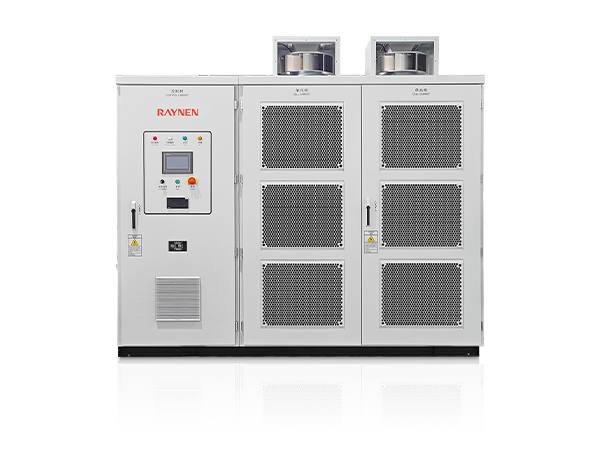
Medium-Voltage Variable Frequency Drives (MV VFDs) are essential power electronic devices used to control the rotational speed, torque, and direction of AC motors operating at voltages typically ranging from 1 kV to 15 kV. Unlike Low-Voltage VFDs, MV drives handle significantly higher power requirements, often extending from hundreds of kilowatts up to over 100 megawatts, making them critical components in large-scale industrial and utility applications.
The primary benefit of deploying MV VFDs is the considerable energy savings achieved by precisely matching motor speed to the required load, particularly in variable torque applications like pumps and fans. Furthermore, they offer superior process control, reduce mechanical stress during motor starts, and provide valuable power quality features such as power factor correction and harmonic mitigation.
Advanced Topologies and Architectural Design of MV VFDs
The internal architecture of MV VFDs is notably more diverse and complex than their low-voltage counterparts due to the necessity of handling high voltages and mitigating harmonic distortion. MV drives generally employ a three-stage design: a converter (rectifier) to transform AC to DC, a DC link for energy storage and smoothing, and an inverter to convert the DC back into variable-frequency AC power for the motor.
Multi-Level Inverter Topologies for Enhanced Output Quality
To produce a more sinusoidal, "motor-friendly" output waveform and limit the voltage rise time ( ) that can damage motor insulation, MV VFDs typically utilize multi-level inverter topologies. These designs synthesize the AC output voltage in multiple steps (levels) rather than two, which is common in low-voltage drives. Two prominent multi-level topologies include:
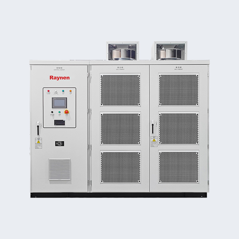
- Cascaded H-Bridge (CHB): This popular voltage source topology uses multiple series-connected, low-voltage H-bridge cells per phase. Each cell has its own input rectifier, and the combined output provides a high-quality, multi-stepped waveform. CHB often requires a complex multi-winding phase-shifting input transformer, which is typically integrated into the drive package.
- Neutral Point Clamped (NPC): The 3-level NPC topology is well-established and utilizes diodes or active switches to clamp the output voltage to a neutral point, creating three voltage levels. It offers a compact design and is suitable for voltages up to around 4.16 kV. Advanced variants like the Active Neutral Point Clamped (ANPC) or higher-level NPC are also used.
Current Source Inverter (CSI) vs. Voltage Source Inverter (VSI) Architectures
MV VFDs can also be broadly categorized based on their DC link component:
- Voltage Source Inverter (VSI): This is the more modern and widely used approach, employing capacitors in the DC link to store and regulate a constant DC voltage. VSI drives use IGBTs in the inverter section and are known for good dynamic performance. Multi-level topologies like CHB and NPC are VSI variants.
- Current Source Inverter (CSI): A mature technology that uses a large inductor in the DC link to maintain a constant DC current. CSI drives often use Gate Turn-Off (GTO) thyristors or more modern devices like SGCTs (Symmetric Gate Commutated Thyristors) in the inverter. They are robust and frequently used in very large power applications or with synchronous motors.
Critical Applications Across Key Industries
The robustness, high power capacity, and precise control offered by MV VFDs make them indispensable across several demanding sectors.
The following table summarizes common MV VFD applications and the process control benefits they deliver:
| Industry | Typical Application | Key Operational Benefit |
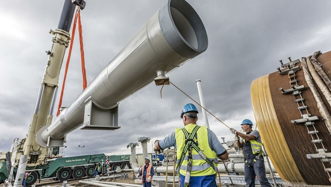
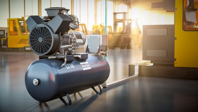
| Oil & Gas | Compressors (Reciprocating and Centrifugal), Pumps | Precise flow and pressure regulation, soft starting, and energy efficiency. |
| Mining & Cement | Crushers, Conveyors, Mills (Ball and Sag) | High starting torque, speed control for optimized crushing/grinding, and reduced mechanical stress. |
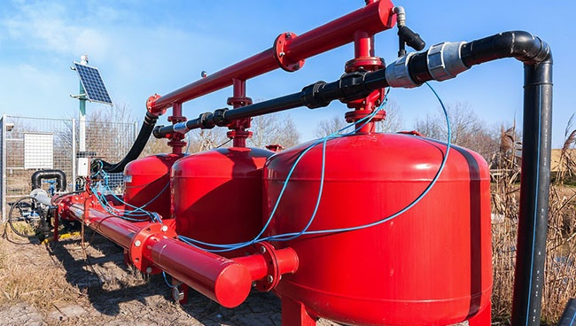
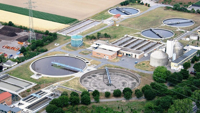
| Utilities (Water/Wastewater) | High-lift Pumps, Blowers | Optimized fluid flow and level control, significant energy savings due to variable torque loads. |
| Power Generation | Boiler Feed Pumps, ID/FD Fans | Improved boiler efficiency, combustion control, and reduced auxiliary power consumption. |
Harmonic Mitigation and Power Quality Considerations
A significant technical consideration for MV VFDs is managing harmonic distortion, which can negatively impact the power grid and other connected equipment. MV VFD designs inherently address this through their multi-pulse and multi-level configurations.
The input section of an MV VFD typically utilizes a multi-pulse diode rectifier (e.g., 18-pulse or 24-pulse) coupled with a phase-shifting transformer. Increasing the pulse count minimizes the magnitude of low-order harmonics injected back into the utility line. Furthermore, some modern drives employ Active Front Ends (AFEs), which replace passive rectifiers with active switches (IGBTs). AFEs are essentially a second inverter that can:
- Actively control and eliminate harmonic distortion, achieving a near-unity input power factor (close to 1.0).
- Allow for regenerative braking, where kinetic energy from the motor is fed back into the power line, a critical feature for loads like cranes and downhill conveyors.
Implementing MV VFDs requires careful system-level design and coordination to ensure compliance with utility standards (such as IEEE 519) and to maximize system reliability and operational benefits.