English
 Español
 عربى
عربى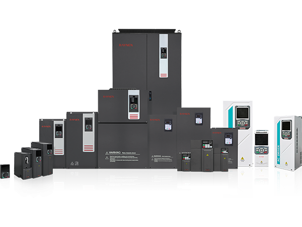


1.Introduction to AC Drives (Variable Frequency Drives) In the realm of modern industrial control an......
READ MOREHome / News / Industry News / Variable Frequency Drive Explained: How It Works, Where It's Used, and How to Get It Right
Variable Frequency Drive Explained: How It Works, Where It's Used, and How to Get It Right
Content
- 1 What Is a Variable Frequency Drive and How Does It Work?
- 2 The Core Operating Principle of a VFD
- 3 Types of Variable Frequency Drives
- 4 Where Variable Speed Drives Are Used
- 5 Key Benefits of Using a Variable Frequency Drive
- 6 Important VFD Specifications and Parameters Explained
- 7 VFD Installation: Common Mistakes and How to Avoid Them
- 8 Programming and Commissioning a Variable Frequency Drive
- 9 Troubleshooting the Most Common VFD Faults
What Is a Variable Frequency Drive and How Does It Work?
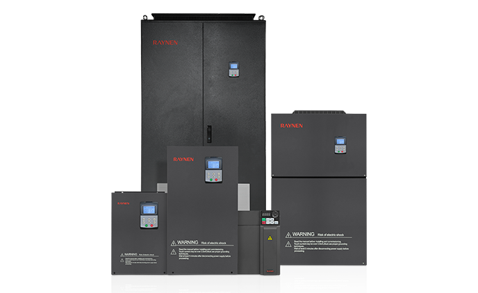
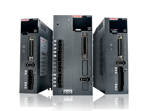
A Variable Frequency Drive (VFD) is an electronic power control device that regulates the speed and torque of an AC electric motor by varying the frequency and voltage of the electrical supply delivered to it. Instead of running a motor at a fixed speed dictated by the supply frequency — typically 50 Hz or 60 Hz depending on the country — a VFD allows operators to dial in exactly the speed the application requires, from near zero all the way up to full rated speed or even beyond in some cases. This precise control over motor output translates directly into energy savings, extended equipment life, and improved process performance across virtually every industry that uses rotating machinery.
Also widely known as a variable speed drive (VSD), adjustable frequency drive (AFD), or inverter drive, the VFD has become one of the most important energy management tools in modern industrial and commercial facilities. The technology is not new — VFDs have been in use since the 1960s — but advances in power electronics, microprocessor control, and cooling technology have made today's drives smaller, more reliable, more affordable, and more capable than any previous generation.
The Core Operating Principle of a VFD
Understanding how a variable frequency drive works internally helps you select the right drive, configure it correctly, and diagnose problems when they arise. Despite the sophisticated electronics inside, the operating principle follows a clear three-stage process: rectification, DC bus filtering, and inversion.
Stage 1 — Rectifier: AC to DC Conversion
The incoming AC supply — single-phase or three-phase depending on the drive size — is first passed through a rectifier section consisting of diodes or thyristors arranged in a bridge configuration. The rectifier converts the alternating current into pulsating DC. Most modern VFDs use a six-pulse diode bridge rectifier for standard applications. Twelve-pulse or active front-end (AFE) rectifiers are used in higher-power or harmonic-sensitive installations to reduce the harmonic distortion fed back into the power supply network.
Stage 2 — DC Bus: Filtering and Energy Storage
The pulsating DC output from the rectifier passes through a DC bus consisting of large filter capacitors and inductors that smooth the voltage into a stable DC link. This DC bus is also where braking energy is managed — when a motor decelerates, it acts as a generator and feeds energy back into the DC bus. This energy can be dissipated through a braking resistor, shared with other drives on a common DC bus, or fed back into the supply grid through a regenerative front end, depending on the drive configuration.
Stage 3 — Inverter: DC to Variable AC
The inverter section is where the VFD's core function is performed. Using Insulated Gate Bipolar Transistors (IGBTs) switched on and off at high frequency under the control of a microprocessor, the inverter synthesizes a variable-frequency, variable-voltage AC output from the stable DC bus voltage. The switching pattern — known as Pulse Width Modulation (PWM) — creates an AC waveform that approximates a true sine wave closely enough for the motor to respond as if it were receiving a clean variable-frequency supply. By adjusting the PWM frequency and pattern, the drive controller can vary both the output frequency (which controls speed) and the output voltage (which controls motor flux and torque) in real time.
Types of Variable Frequency Drives
Not all VFDs are built the same way or suited to the same applications. The major drive types differ in their control sophistication, motor compatibility, and performance characteristics. Choosing the right type for your application is as important as choosing the right power rating.
| VFD Type | Control Method | Key Strengths | Typical Applications |
| V/f (Volts per Hertz) | Open-loop scalar control | Simple, low cost, robust | Fans, pumps, conveyors |
| Sensorless Vector | Open-loop vector control | Better torque at low speed, no encoder needed | Compressors, mixers, general machinery |
| Closed-Loop Vector (FOC) | Field-oriented control with encoder feedback | Precise speed and torque control across full range | CNC machines, hoists, winders |
| Direct Torque Control (DTC) | Direct control of flux and torque | Fastest torque response, no encoder required | Paper mills, steel rolling, cranes |
| Regenerative VFD | Active front end with grid feedback | Returns braking energy to grid, low harmonics | Elevators, test benches, regenerative loads |
Where Variable Speed Drives Are Used
Variable frequency drives are found in almost every sector of modern industry and commerce. Anywhere an electric motor drives a load where speed control, soft starting, or energy efficiency is beneficial, a VFD is likely the right solution. The following industries represent the largest and most impactful applications.
HVAC Systems: Fans and Pumps
Heating, ventilation, and air conditioning systems represent one of the single largest application areas for variable frequency drives. Centrifugal fans and pumps follow the Affinity Laws — a physical relationship meaning that reducing a fan or pump speed by just 20% reduces its power consumption by approximately 49%, because power scales with the cube of speed. A building's air handling unit running at 80% speed instead of 100% uses roughly half the electrical energy, with no impact on comfort when properly controlled. In large commercial buildings, VFD-controlled HVAC systems routinely deliver energy savings of 30–50% compared to fixed-speed operation with throttling valves or dampers.
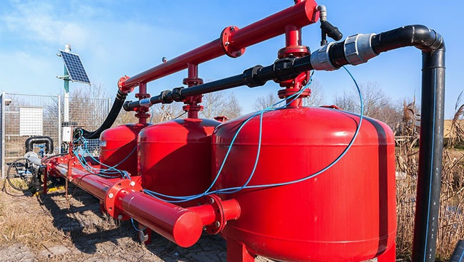
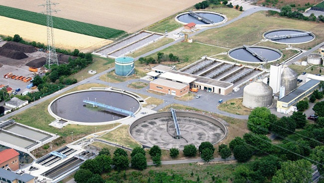
Water and Wastewater Treatment
Municipal water utilities and industrial wastewater treatment plants use adjustable frequency drives on pumping stations, aeration blowers, and mixing systems. Pump speed is modulated to match demand in real time — maintaining constant system pressure regardless of fluctuating flow demand — eliminating the pressure surges and water hammer that occur with fixed-speed pumps cycling on and off. VFDs on aeration blowers in wastewater treatment plants allow dissolved oxygen levels to be controlled precisely, improving biological treatment efficiency while reducing blower energy consumption by 20–40%.
Manufacturing and Process Industries
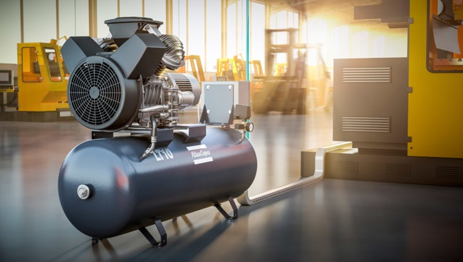
Conveyors, extruders, mixers, compressors, and machine tool spindles all benefit from variable speed drive control. In food and beverage processing, VFDs allow conveyor speeds to be synchronized across multiple production stages, eliminating product jams and reducing mechanical stress on the conveyor structure. In plastics extrusion, precise screw speed control via VFD is essential for consistent melt quality and dimensional accuracy of the extruded product. In compressor applications, VFD-controlled variable speed compressors maintain constant discharge pressure while consuming only the energy the process actually demands — eliminating the loading/unloading cycles of fixed-speed compressors that waste significant energy in partial-load conditions.
Oil and Gas
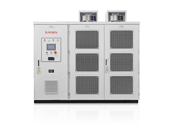
Submersible pump motors in oil wells, pipeline booster pumps, gas compression systems, and offshore platform equipment operate under challenging conditions where VFD control delivers both energy savings and the ability to optimize production rates. Variable frequency drives rated for hazardous area installation — certified to ATEX or IECEx standards — are used in environments where flammable gases or dusts are present. High-power medium-voltage VFDs (above 690V) are used for the large motors driving major compressors and pipeline pumps in this sector.
Renewable Energy
Wind turbines use variable frequency drives to decouple the generator speed from the grid frequency, allowing the turbine rotor to operate at the optimal speed for the prevailing wind conditions regardless of what frequency the grid requires. This maximum power point tracking (MPPT) capability, enabled by the VFD, is fundamental to the efficiency of modern variable-speed wind turbines. Solar pumping systems also use VFDs to match pump output to available solar panel power, eliminating the need for battery storage in many irrigation applications.

Key Benefits of Using a Variable Frequency Drive
The business case for installing variable speed drives is typically compelling across a wide range of applications. The benefits extend beyond energy savings to include mechanical, operational, and maintenance advantages that together make VFDs one of the highest-return capital investments in industrial energy management.
- Major energy savings: For variable-torque loads like fans and pumps, the cubic relationship between speed and power means even modest speed reductions yield large energy savings. A pump running at 75% of full speed consumes only about 42% of the energy it would use at full speed. Across a large facility with dozens of motors, the cumulative savings can represent hundreds of thousands of dollars annually.
- Soft starting eliminates inrush current: When a motor starts direct-on-line, it draws 6–8 times its full-load current for several seconds. This inrush current stresses the motor windings, mechanical drivetrain, and electrical infrastructure. A VFD ramps voltage and frequency up gradually, limiting starting current to 1.5–2 times full-load current. This protection dramatically extends motor and driven equipment life and reduces electrical infrastructure sizing requirements.
- Precise process control: Speed can be controlled to within fractions of a percent using feedback from pressure transducers, flow meters, temperature sensors, or other process instruments connected to the drive's analog inputs. This closed-loop control maintains process variables at setpoint without the hunting and overshoot of simpler on/off control strategies.
- Reduced mechanical wear: Eliminating hard starts and stops, reducing peak torques, and allowing controlled deceleration all reduce wear on couplings, gearboxes, belts, and bearings. Extended mechanical component life directly reduces maintenance costs and unplanned downtime — often delivering payback equal to or exceeding the energy savings in maintenance-intensive applications.
- Built-in motor protection: Modern VFDs include comprehensive motor protection functions — overload protection, phase loss detection, ground fault detection, overvoltage and undervoltage trips, and motor thermistor monitoring — that replace or supplement separate protection relays. A single VFD can protect both the drive and the motor, simplifying the electrical panel and reducing component count.
- Reduced noise and vibration: Running fans and pumps at the minimum speed required by the process rather than full speed reduces aerodynamic noise significantly. In commercial buildings, VFD-controlled air handling units are measurably quieter — an important factor in offices, hospitals, and schools where acoustic comfort matters.
Important VFD Specifications and Parameters Explained
Selecting the correct variable frequency drive requires understanding the key specifications on the datasheet and matching them to your motor and application requirements. Undersizing a drive leads to overload trips and premature failure; oversizing wastes capital and can cause control instability at light loads.
| Specification | What It Means | Selection Guidance |
| Output power (kW / HP) | Maximum motor power the drive can handle continuously | Match to motor nameplate kW; consider derating for altitude/temperature |
| Output current (A) | Continuous current capacity — more important than kW for motor matching | Must exceed motor full-load amps (FLA) at worst-case conditions |
| Overload capacity | Short-term current above rating (e.g., 150% for 60 seconds) | Heavy-duty loads need higher overload rating than light-duty |
| Input voltage and phases | Supply voltage compatibility (e.g., 400V 3-phase, 230V 1-phase) | Must match available supply; check voltage tolerance range |
| PWM switching frequency | IGBT switching rate; higher = smoother waveform, more IGBT heat | 4–8 kHz typical; higher for low-noise applications; derate drive at high frequency |
| Protection rating (IP) | Enclosure protection against dust and water ingress | IP20 for clean panels; IP54/IP55 for dusty or wet environments |
| Communication protocols | Industrial network interfaces for automation integration | Modbus RTU, Profibus, EtherNet/IP, Profinet — match to your PLC/SCADA |
VFD Installation: Common Mistakes and How to Avoid Them
A correctly specified VFD that is poorly installed will underperform, cause interference with other equipment, and fail prematurely. The following installation issues are the most frequently encountered in the field and are entirely preventable with proper planning.
Cable Length and Motor Cable Selection
The PWM output of a VFD generates high-frequency voltage reflections on long motor cables — a phenomenon called voltage reflection or cable resonance — that can create voltage spikes at the motor terminals significantly exceeding the drive's output voltage. On cables longer than approximately 30–50 meters, these spikes can damage motor winding insulation. Use VFD-rated motor cables (shielded, with low capacitance) and install output filters or dV/dt reactors when cable runs exceed the drive manufacturer's specified maximum length. Always connect the cable shield to ground at both the drive and motor ends.
Grounding and EMC Compliance
Variable frequency drives generate significant high-frequency electrical noise due to their IGBT switching. Without proper EMC (electromagnetic compatibility) measures, this noise can interfere with nearby sensitive equipment including PLCs, instrumentation, and communication systems. Install the VFD in a metal enclosure bonded to the building ground system. Use screened motor cables with 360-degree screen termination at EMC cable glands. Install EMC line filters on the input if required by the installation environment or regulatory standards. Keep power and signal cables physically separated in cable trays.
Harmonic Distortion and Input Filters
The rectifier section of a standard VFD draws non-sinusoidal current from the supply, injecting harmonic currents into the electrical network. In facilities with many drives or other non-linear loads, these harmonics can cause transformer overheating, capacitor bank failures, and nuisance tripping of sensitive equipment. Where harmonic levels exceed IEEE 519 or EN 61000-3-12 limits, install DC link chokes (reactors) inside the drive, AC line reactors on the input, or specify active front-end drives that draw near-sinusoidal input current.
Programming and Commissioning a Variable Frequency Drive
After physical installation, a VFD must be correctly programmed before it is put into service. Out-of-the-box default settings are designed for a generic motor and load — they will run most motors but will not deliver optimal performance, protection, or energy efficiency for your specific application. The following parameters should be configured during commissioning:
- Motor nameplate data: Enter the motor's rated voltage, rated current, rated frequency, rated speed (RPM), and power factor from the motor nameplate. This allows the drive's motor model to calculate correct flux and torque references. On drives with auto-tune capability, run the auto-tune function to identify motor-specific electrical parameters automatically.
- Minimum and maximum frequency limits: Set minimum output frequency to prevent the motor from running below a safe speed for continuous operation (typically 5–20 Hz depending on motor cooling method). Set maximum frequency to match the maximum allowable mechanical speed of the driven equipment — overspeeding a pump or fan beyond its design rating can cause catastrophic mechanical failure.
- Acceleration and deceleration ramps: Set ramp times appropriate for the load inertia and process requirements. Too-fast acceleration on high-inertia loads causes overcurrent trips; too-slow deceleration on loads that must stop quickly is a safety hazard. For applications with high inertia and fast required deceleration, a braking resistor or regenerative unit will be needed.
- Speed reference source: Configure whether the speed setpoint comes from the drive's keypad, an analog 4–20mA or 0–10V signal, a digital preset speed, a fieldbus command, or a PID controller output. For most process applications, a PID loop inside the drive — with feedback from a pressure or flow sensor — provides the most energy-efficient control.
- Skip frequencies: Some mechanical systems have resonant frequencies at which vibration becomes severe if the motor is run continuously at that speed. Program skip frequency bands to prevent the drive from running continuously at those critical speeds — it will accelerate through them but never dwell at them.
Troubleshooting the Most Common VFD Faults
Modern variable frequency drives have comprehensive self-diagnostic capabilities and display fault codes that identify the type of fault that caused a trip. Understanding the most common fault types and their root causes allows maintenance personnel to restore operation quickly and address underlying issues before they cause drive or motor damage.
- Overcurrent (OC) fault: The drive output current has exceeded the instantaneous trip threshold. Common causes include acceleration ramp too fast for the load inertia, mechanical jam in the driven equipment, incorrect motor data entered causing the drive to over-flux the motor, or a failing motor with shorted turns. Check mechanical load freedom, review ramp settings, and verify motor parameters.
- Overvoltage (OV) fault: The DC bus voltage has exceeded the drive's maximum threshold. Almost always caused by regenerative energy from a rapidly decelerating high-inertia load charging the DC bus faster than the braking resistor can dissipate it. Extend the deceleration ramp time, verify the braking resistor is correctly sized and connected, or consider a regenerative drive for high-cycle or high-inertia applications.
- Overtemperature (OH) fault: The drive's heatsink or internal ambient temperature has exceeded safe limits. Causes include inadequate ventilation in the enclosure, high ambient temperature, blocked cooling fans or heatsink fins, or excessive switching frequency setting. Clean heatsink fins, verify enclosure ventilation airflow, check cooling fan operation, and consider derating the drive or providing forced cooling.
- Ground fault (GF) fault: Current is flowing from the drive output to ground, indicating damaged motor cable insulation, moisture in the motor terminal box, or a failed motor winding. Disconnect the motor and cable, check insulation resistance with a megohmmeter, and identify and repair the fault location before restarting.
- Input phase loss fault: One phase of the three-phase input supply is missing or has low voltage. This causes the DC bus to charge from only two phases, increasing ripple voltage and thermal stress on the DC bus capacitors. Check input fuses, contactor contacts, and upstream supply connections immediately — running a three-phase VFD on two phases will cause rapid capacitor and rectifier failure.
Previous Post
The Complete Guide to Industrial Servo Motors: How They Work and Why They Matter
Next Post
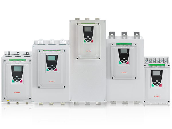
Low-Voltage Soft Starters: What They Are, How They Work, and How to Pick the Right One
Copyright 2024 Fujian Raynen Technology Co.,Ltd. All Rights Reserved.
Privacy Policy  Motor Control Manufacturers