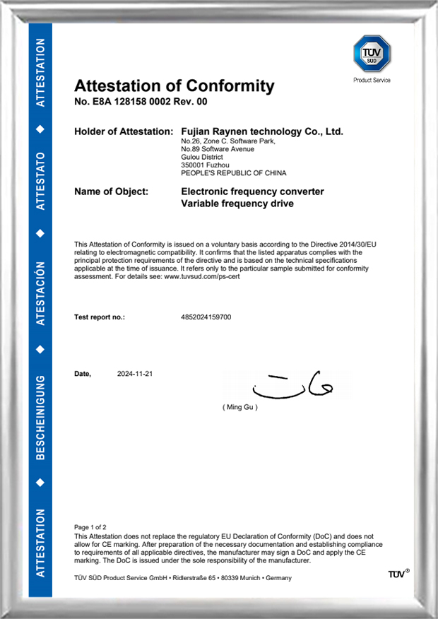
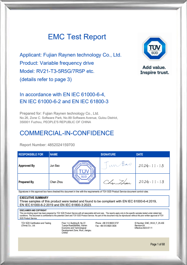
English
 Español
 عربى
عربى
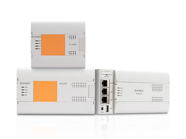


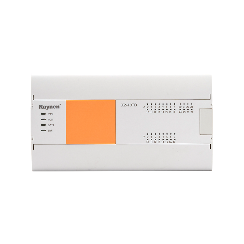
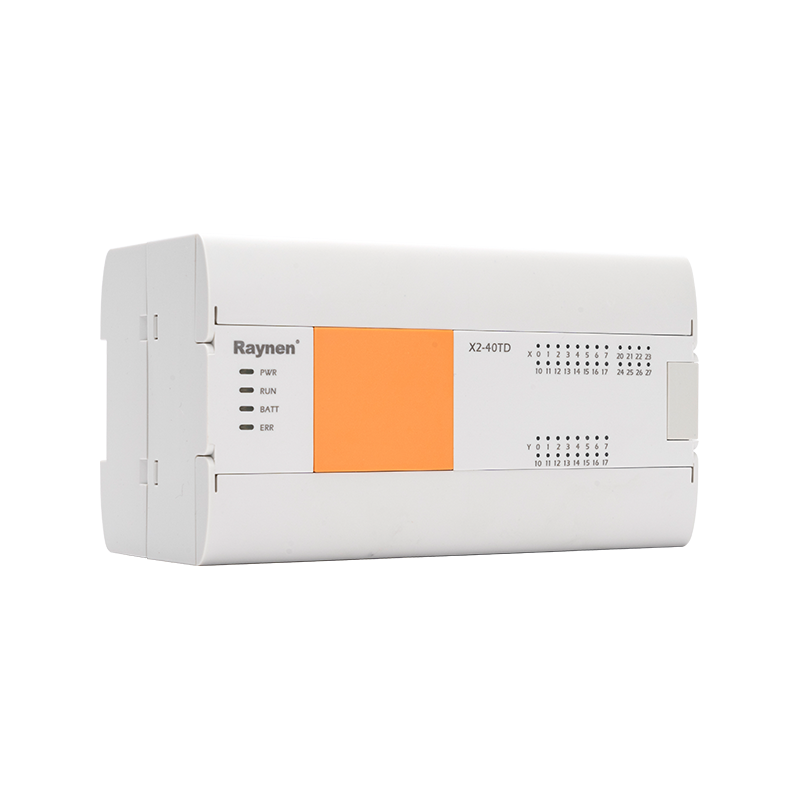
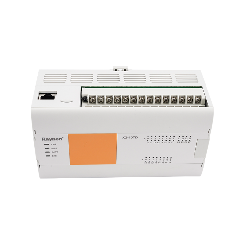
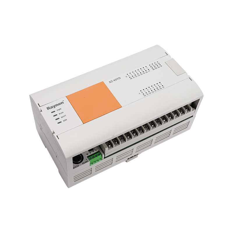
X2 series summary
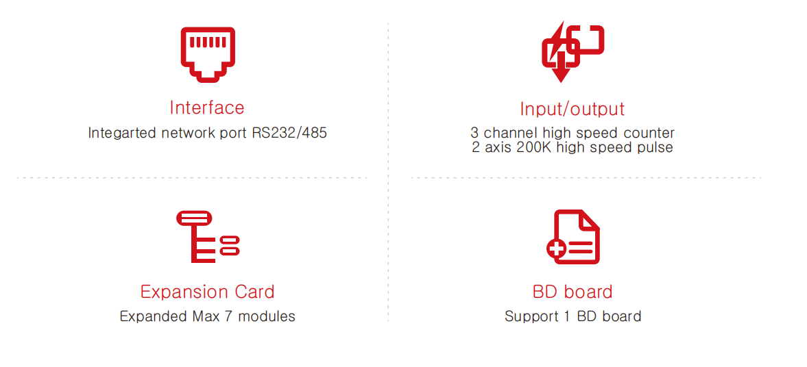
With linear interpolation, two-axis high-speed pulse output high-speed counting and other motion control function;
Real-time clock, power outage data is permanently stored;
It supports a BD expansion board and can expand up to 7modules.
Advantage
X2 series parameter
|
Item |
Power Specification |
|||
|
X2-24TD |
X2-32TD |
X2-40TD |
X2-60TD |
|
|
Power consumption |
10W |
12W |
12W |
14W |
|
Power Voltage |
DC24V |
|||
|
Voltage range |
DC 20.4~28.8V |
|||
|
Allow instantaneous power outage time |
For transient power outages below 5ms, the operation will continue |
|||
|
Power fuse |
60V 2A |
|||
|
Impulse current |
12A, 0.5ms below/28.8V DC |
|||
|
DC24V given power |
300mA below |
|||
|
DC5V build-in power |
800mA below |
|||
|
Item |
Input Specification |
||||
|
X2-24TD |
X2-32TD |
X2-40TD |
X2-60TD |
||
|
Input number |
14 |
16 |
24 |
36 |
|
|
High-speed counter |
Single phase 200KHz[3 pcs], AB phase 100KHz[3 pcs] |
||||
|
Input type |
Sink type/source type |
||||
|
Input signal voltage |
DC source type: DC20.4V~28.8V |
||||
|
Input impedance |
X0-X5 |
3.3K |
|||
|
X6-X7 |
5.6K |
3.3K |
|||
|
X10 above |
- |
5.6K |
|||
|
ON input inductance current |
X0-X5 |
5mA above |
|||
|
X6-X7 |
4mA |
5mA above |
|||
|
X10 above |
- |
4mA above |
|||
|
OFF Input induced current |
1mA above |
||||
|
Input response time |
<4.5ms |
||||
|
Input signal form |
No voltage contact input |
||||
|
Sink input: NPN open-collector transistor |
|||||
|
Source input: PNP open-collector transistor |
|||||
|
Input loop isolation |
Optocoupler isolation |
||||
|
Display of input actions |
The LED on the panel lights up when the optocoupler is driven |
||||
|
Item |
Power Specification |
||||
|
X2-24TD |
X2-32TD |
X2-40TD |
X2-60TD |
||
|
Output number |
10 |
16 |
16 |
24 |
|
|
Pulse frequency( Max) |
Single-ended 2-axis 200K |
||||
|
Output type |
Transistor/Leaky output |
||||
|
External power supply |
DC5~30V |
||||
|
Max load |
Resistive load |
0.5A/way |
|||
|
Inductive load |
12W/DC24V |
||||
|
Lamp load |
5W/DC24V |
||||
|
Mid load |
5mA(DC5~24V) |
||||
|
Response |
OFF→ON |
High speed: 5μs below/10mA above(DC5~24V) |
|||
|
Common: 0.2ms below/200mAabove(DC24V) |
|||||
|
ON→OFF |
High speed: 5μs below/10mA above(DC5~24V) |
||||
|
Common: 0.2ms below/200mAabove(DC24V) |
|||||
|
Loop isolation |
Optocoupler isolation |
||||
|
Display of output actions |
The LED on the panel lights up when the optocoupler is driven |
||||
X2 series: software component resources
|
Item |
Conten |
|
|
Input relay X |
256 point |
X0~×377 |
|
Output relay Y |
256 point |
Y0~Y377 |
|
Auxiliary relay M |
7680 point |
M0~Latch start(Set the power off non-hold area) |
|
Latch start~latch end (Set power hold area, Max M1023) |
||
|
Latch End~M7679(Fixed power hold area) |
||
|
Special auxiliary relay SM |
512 point |
SM8000~SM8511 |
|
Status relay S |
4096 point |
S0~S4095 |
|
timer T |
200 point |
T0~T199(100ms Time base) |
|
T192~T199(Subroutine specialization) |
||
|
46 point |
T200~T245(10ms time base) |
|
|
4 point |
T246~T249(1ms Cumulative type) |
|
|
6 point |
T250~T255(100ms Cumulative type) |
|
|
256 point |
T256~T511(1ms time base) |
|
|
Counter 16-bit |
200 point |
C0~C199 |
|
Counter 32-bit |
56 point |
C200~C234 |
|
High Speed counter |
- |
C235~C255 |
|
Data register D |
8000 point |
D0~D7999 |
|
Special data register SD |
512 point |
SD8000~SD8511 |
|
Index register |
16 point |
V0~V7, Z0~Z7 |
|
Expansion register |
32768 point |
R0~R32767 |
|
Pointer |
4096 point |
P0~P4095 |
|
Interrupted |
6 point |
100*~150*Input interrupt |
|
3 point |
16**~18**Timing interrupt |
|
|
6 point |
1010~1060 High-speed counter interrupt |
|
|
Master control with nesting |
8 point |
NO~N7 |
|
constant K |
- |
16 bit range: -32768~+32767, 32 bit range: -2147483648~+2147483647 |
|
constant H |
- |
16 bit range: 0~FFFF, 32 bit range: 0~FFFFFFFF |
|
Real number(E) |
- |
-3.40×10⁻⁸~-1.17×1038, 1.17x10-⁸~3.40×10³8 |
|
Character string |
- |
The maximum length of a half-corner character framed by""is 32 characters |
X2 series high-speed counter
|
Distribution Input |
Single-phase single counter |
Single-phase double counter |
AB Phase counter |
|||||||||||||
|
C235 |
C236 |
C237 |
C238 |
C239 |
C240 |
C243 |
C244 |
C246 |
C247 |
C248 |
C249 |
C251 |
C252 |
C253 |
C254 |
|
|
XO |
U/D |
U/D |
U |
U |
A |
A |
||||||||||
|
X1 |
U/D |
R |
D |
D |
B |
B |
||||||||||
|
X2 |
U/D |
U/D |
U |
R |
R |
A |
||||||||||
|
X3 |
U/D |
R |
D |
S |
B |
|||||||||||
|
X5 |
U/D |
S |
U |
A |
||||||||||||
|
X6 |
U/D |
D |
B |
|||||||||||||
X2 series size
|
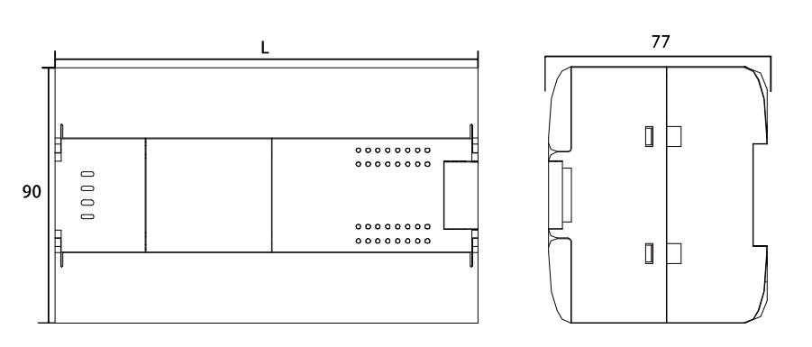
PLC model |
L |
|
X2-24TD-E0 |
132 |
|
X2-32TD-E0 |
150 |
|
X2-40TD-E0 |
165 |
|
X2-60TD-E0 |
210 |
X2 series wire drawing
-3(4)kW VFD")
-15(18)kW VFD")
kW VFD")
-315(355)kW VFD")