English
 Español
 عربى
عربى
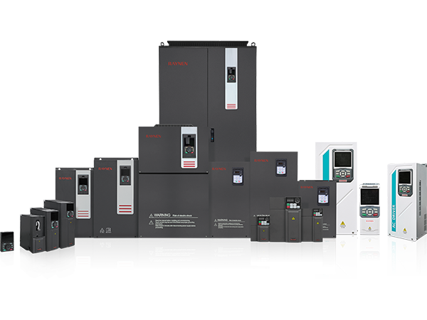
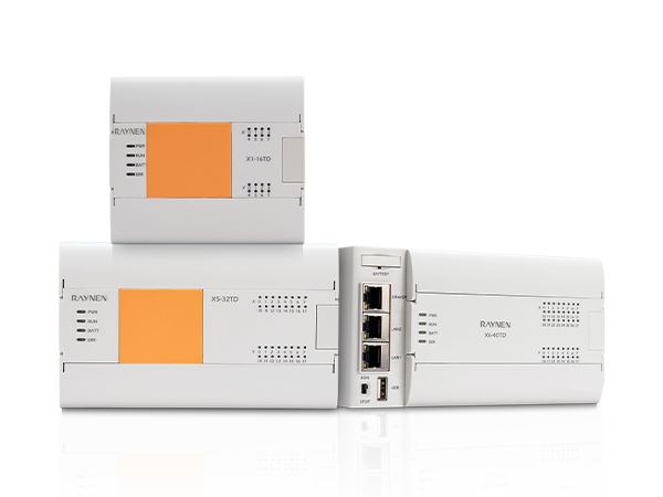
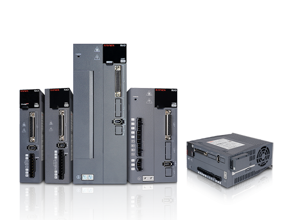
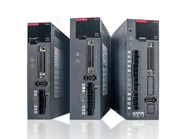
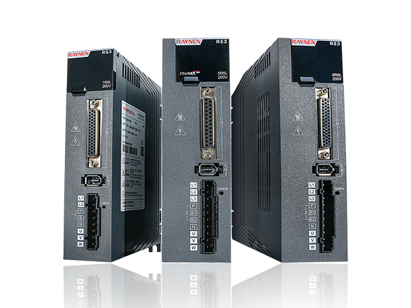
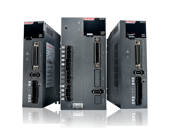








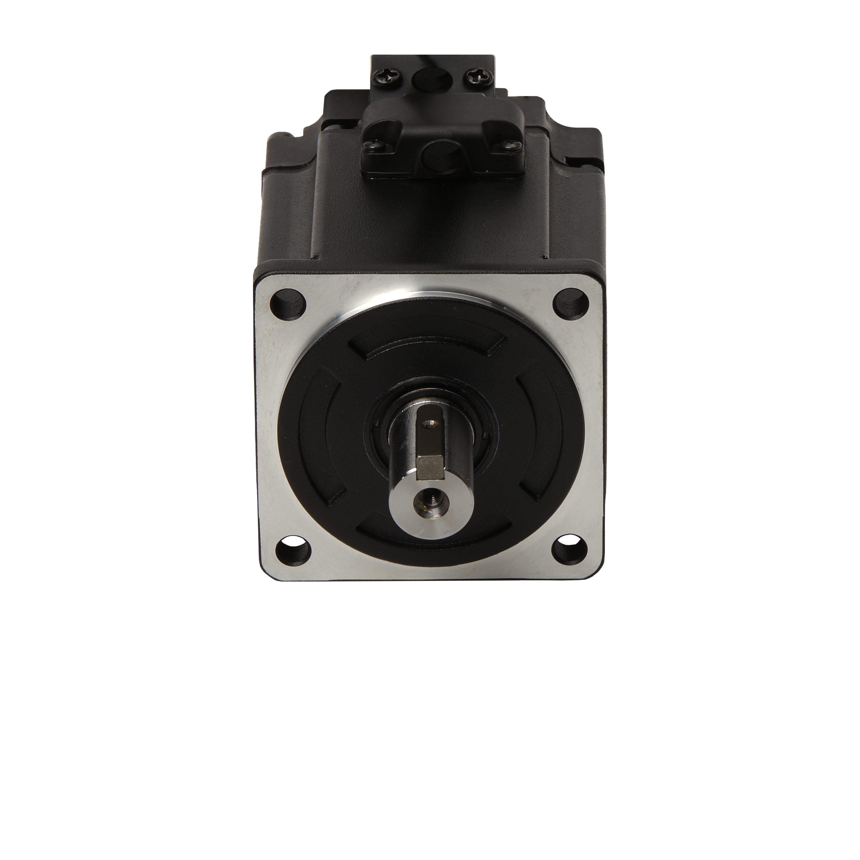
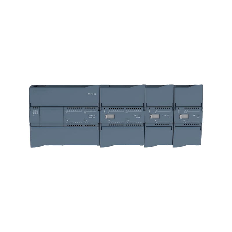

The RN1200 series PLC is an efficient automation control device designed specifically for small and medium-sized projects. It provides a wide range of I/O modules that can be seamlessly compatible with S71200 PLC for use.
This series of products is simple to use, flexible and comprehensive, and can expand or replace corresponding functions in existing automation systems, improving the flexibility and reliability of the system.
Especially suitable for small and medium-sized projects and OEM markets, it can be applied to various industries such as municipal facilities, equipment manufacturing, new energy, energy storage, logistics and transportation.
Extension Module
Technical Specification for Digital Input Module
|
Extension Module |
||
|
Technical Specification for Digital Input Module |
||
|
Model |
SM 1221 DI8×24 VDC |
SM 1221 DI16×24 VDC |
|
Order Number |
RN 221-1BF32-0XB0 |
RN 221-1BH32-0XB0 |
|
Routine |
||
|
Dimensions (W * H * D) |
45*100*75mm |
|
|
Power Consumption |
1.5W |
2.5W |
|
Current Consumption (Sm Bus) |
105mA |
130mA |
|
Current Consumption (24VDC) |
Input 4mA per point used |
|
|
Digital Input |
||
|
Input Points |
8 |
16 |
|
Input Type |
PNP/NPN |
|
|
Rated Voltage |
24 VDC,4mA |
|
|
Maximum Continuous Allowable Voltage |
30 VDC |
|
|
Surge Voltage |
35 VDC,0.5s |
|
|
Logic 1 [minimum] |
At 15 VDC, 2.5mA |
|
|
Logic 0 [maximum] |
1mA at 5 VDC |
|
|
Isolation Group |
2 |
4 |
|
Filtering Time |
0.2、0.4、0.8、1.6、3.2、6.4、12.8ms |
|
|
Simultaneously Connect Input Numbers |
8 |
16 |
|
Isolation (On-Site and Logical Side) |
707 VDC (type test) |
|
|
Cable Length (Maximum) |
500 meters (shielded), 300 meters (unshielded) |
|
|
Model |
SM 1222 DQ8X RLY |
SM 1222 DQ16X RLY |
SM 1222 DQ 8X24 VDC |
SM 1222 DQ 16X24 VDC |
|
Order Number |
RN 222-1HF32-0XB0 |
RN 222-1HH32-0XB0 |
RN 222-1BF32-0XB0 |
RN 222-1BH32-0XB0 |
|
Routine |
||||
|
Dimensions (W * H * D) |
45*100*75mm |
|||
|
Power Consumption |
3W |
4.5W |
1.5W |
2.5W |
|
Current Consumption (Sm Bus) |
120mA |
135mA |
120mA |
140mA |
|
Current Consumption (24vdc) |
Each relay coil used has 7mA |
50mA |
100mA |
|
|
Digital Output |
||||
|
Number of Output Points for Digital Quantity |
8 Relay outputs |
16 Relay outputs |
8-transistor output |
16-transistor output |
|
Output Type |
Dry contacts, relays |
Dry contacts, relays |
Solid state MOSFET, source type |
Solid state MOSFET, source type |
|
Voltage Range |
5~30 VDC or 5~250 VAC |
20.4~28.8V |
20.4~28.8V |
|
|
Logic 1 Signal at Maximum Current |
- |
- |
Minimum 20V |
Minimum 20V |
|
Logic 0 Signal with 10k ω Load |
- |
Maximum 0.1V |
Maximum 0.1V |
|
|
Current (Maximum) |
2A |
2A |
0.5A |
0.5A |
|
Lamp Load [maximum] |
30W DC/200W AC |
30W DC/200W AC |
5W |
5W |
|
On State Contact Resistance |
The maximum resistance of the new device is 0.2 Ω |
The maximum resistance of the new device is 0.2 Ω |
Maximum 0.6Ω |
Maximum 0.6Ω |
|
Leakage Current at Each Point |
- |
1 |
Maximum 10 μ A |
Maximum 10 μ A |
|
Inrush Current |
7A when the contact is closed |
7A when the contact is closed |
8A, Maximum duration of 100ms |
8A, Maximum duration of 100ms |
|
Overload Protection |
Nothing |
Nothing |
Nothing |
Nothing |
|
Isolation (On-Site and Logical Side) |
1500 VAC (coil and contacts) None (coil and logic side) |
707 VDC(Type testing) |
707 VDC(Type testing) |
|
|
Isolation Group |
2 |
4 |
1 |
1 |
|
Current at Each Common Terminal (Maximum) |
10A |
10A |
4A |
8A |
|
Inductive Clamp Voltage |
- |
L+-48V, 1W loss |
L+-48V, 1W loss |
|
|
Switch Delay |
Maximum 10ms |
Maximum 10ms |
The maximum duration from disconnection to connection is 50us/from connection to disconnection is 200us |
|
|
Mechanical Life Cycle |
10000000 open/close cycles |
|||
|
Contact Life Under Rated Load |
100000 open/close cycles |
|||
|
Behavior During Run-Stop |
Previous value or replacement value (default value is 0) |
|||
|
Number of Outputs Connected Simultaneously |
8 |
16 |
8 |
16 |
|
Cable Length (Maximum) |
500 meters (shielding); 150 meters (unshielded) |
|||
|
Model |
SM 1223 DI8×24 VDC DQ 8×RLY |
SM 1223 DI16×24 VDC DQ 16×RLY |
SM 1223 DI8×24 VDC DQ 8×24VDC |
SM 1223 DI16×24 VDC DQ 16×24VDC |
|
Order Number |
RN 223-1PH32-0XB0 |
RN 223-1PL32-0XB0 |
RN 223-1BH32-0XB0 |
RN 223-1BL32-0XB0 |
|
Routine |
||||
|
Dimensions (W * H * D) |
45*100*75mm |
70*100*75mm |
45*100*75mm |
70*100*75mm |
|
Power Consumption |
5.5W |
10W |
2.5W |
4.5W |
|
Current Consumption (Sm Bus) |
145mA |
180mA |
145mA |
185mA |
|
Current Consumption (24vdc) |
Each point used inputs 4mA/each relay coil used 7mA |
150mA |
200mA |
|
|
Digital Input |
||||
|
Input Points |
8 |
16 |
8 |
16 |
|
Input Type |
Leakage type/source type (IEC1 leakage type) |
Logic 1 signal (minimum) |
15 VDC at 2.5 mA |
|
|
Rated Voltage |
24 VDC at 4 mA, rated value |
Logic 0 signal (maximum) |
1 mA 时 5 VDC |
|
|
Allowable Continuous Voltage |
Maximum 30 VDC |
Isolation (on-site and logical side) |
707 VDC (type test) |
|
|
Surge Voltage |
35 VDC, Continuous for 0.5 seconds |
|||
|
Cable Length (Maximum) |
500 meters (shielded), 300 meters (unshielded) |
|||
|
Number of Inputs Connected Simultaneously |
8 |
16 |
8 |
16 |
|
Filtering Time |
0.2, 0.4, 0.8, 1.6, 3.2, 6.4, and 12.8ms (optional, 4 in a group) |
|||
|
Digital Output |
||||
|
Output Points |
8 |
16 |
8 |
16 |
|
Output Type |
Dry contacts, relays |
Dry contacts, relays |
Solid state MOSFET, source type |
Solid state MOSFET, source type |
|
Voltage Range |
5~30VDC or 5~250VAC |
20.4~28.8V |
20.4~28.8V |
|
|
Logic 1 Signal at Maximum Current |
- |
- |
Minimum 20 VDC |
Minimum 20 VDC |
|
Logic 0 Signal with 10k ω Load |
- |
- |
Maximum 0.1 VDC |
Maximum 0.1 VDC |
|
Current (Maximum) |
2 A |
2 A |
0.5 A |
0.5 A |
|
Lamp Load |
30 W DC/200 W AC |
30 W DC/200 W AC |
5 W |
5 W |
|
On State Contact Resistance |
The maximum resistance of the new device is 0.2 Ω |
The maximum resistance of the new device is 0.2 Ω |
Maximum 0.6Ω |
Maximum 0.6Ω |
|
Leakage Current at Each Point |
- |
Maximum 10μA |
Maximum 10μA |
|
|
Inrush Current |
When the contact is closed, it is 7 A |
When the contact is closed, it is 7 A |
8A, Maximum duration of 100 ms |
8A, Maximum duration of 100 ms |
|
Overload Protection |
Nothing |
Nothing |
Nothing |
Nothing |
|
Isolation (On-Site and Logical Side) |
1500 VAC (coil and contacts) None (coil and logic side) |
707 VDC(Type testing) |
707 VDC(Type testing) |
|
|
Current at Each Common Terminal |
10A |
8A |
4A |
8A |
|
Inductive Clamp Voltage |
- |
L+-48 V, 1 W loss |
L+-48 V, 1 W loss |
|
|
Switch Delay |
Maximum 10 ms |
Maximum 10 ms |
The maximum duration from disconnection to disconnection is 50 μ s/200 μ s |
|
|
Mechanical Lifespan (No Load) |
10000000 open/close cycles |
- |
- |
|
|
Contact Life Under Rated Load |
100000 open/close cycles |
- |
- |
|
|
Behavior of RUN-STOP |
Previous value or replacement value (default value is 0) |
|||
|
Number of Outputs Connected Simultaneously |
8 |
16 |
8 |
16 |
|
Cable Length (Maximum) |
500 meters (shielding); 150 meters (unshielded) |
|||
Technical Specification for Analog Input Module
|
Model |
SM 1231 AI 4X13 bit |
SM1231 AI8X13 bit |
|
Order Number |
RN 231-4HD32-0XBO |
RN 231-4HF32-0XBO |
|
Routine |
||
|
Dimensions (W * H * D) |
45*100*75mm |
|
|
Power Consumption |
2.2W |
2.3W |
|
Current Consumption (Sm Bus) |
80 mA |
90 mA |
|
Current Consumption (24vdc) |
45 mA |
45 mA |
|
Analog Input |
||
|
Number of Input Channels |
4 |
8 |
|
Type |
Voltage or current (differential): 2 can be selected as a group |
|
|
Scope |
± 10V, ± 5V, ± 2.5V, 0-20 mA or 4-20 mA |
|
|
Full Range (Data Words) |
-27648-27648, voltage; 0~27648, current |
|
|
Overrush/Downrush Range (Data Word) |
Voltage: 32511~27649/-27649~-32512 Current: 32511~27649/0~-4864 |
|
|
Overflow/Underflow Range (Data Words) |
Voltage: 32767~32512/-32513~-32768 Current 0-20 mA: 32767~32512/-4865~-32768 Current 4-20mA: 32767-32512/value less than -4864 indicates an open circuit |
|
|
Precision |
12 bits+symbol bit |
|
|
Maximum Voltage/Current Resistance |
±35V/±40 mA |
|
|
Smooth |
None, weak, moderate, or strong |
|
|
Noise Suppression |
400, 60, 50 or 10 Hz |
|
|
Impedance |
≥ 9 M Ω (voltage)/≥ 270 Ω,<290 Ω (current) |
|
|
Accuracy (25 ℃/0-55 ℃) |
± 0.1%/± 0.2% of full range |
|
|
Common-Mode Rejection |
40 dB,DC-60Hz |
|
|
Working Signal Range |
The signal plus common mode voltage must be less than +12V and greater than-12V |
|
|
Cable Length (Maximum) |
100 meters, shielded twisted pair cable |
|
|
Isolation (on-site side and logic side/logic side and 24 VDC/on-site side and 24 VDC/channel and channel) None |
||
|
Diagnosis |
||
|
Overflow/Underflow |
√ 1 |
|
|
Short Circuit to Ground (Voltage Mode Only) |
Not applicable |
|
|
Open Circuit (Current Mode Only) |
Only within the range of 4-20 mA (if the input is below -4864; 1.185 mA) |
|
|
24VDC Low Voltage |
√ |
|
Technical Specification for Analog Output Module
|
Model |
SM 1232 AQ 2X14 bit |
SM 1232 AQ 4X14 bit |
|
Order Number |
RN 232-4HB32-0XB0 |
RN 232-4HD32-0XB0 |
|
Routine |
||
|
Dimensions (W * H * D) |
45*100*75mm |
|
|
Power consumption |
1.8W |
2W |
|
Current consumption (SM bus) |
80 mA |
|
|
Current consumption (24VDC) |
45 mA (no load) |
|
|
Analog Output |
||
|
Output Path |
2 |
4 |
|
Type |
Voltage or current |
|
|
Scope |
± 10V, 0-20 mA or 4-20 mA |
|
|
Resolution |
Voltage: 14 bits; Current: 13 bits |
|
|
Full range (data words) |
Voltage: -276648~27648; Current: 0-27648 |
|
|
Accuracy (25 ℃/0-55 ℃) |
± 0.3%/± 0.6% of full range |
|
|
Stabilization time (95% of new value) |
Voltage: 300 μ s (R), 750 μ s (1uF); Current: 600 μ s (1mH), 2ms (10 mH) |
|
|
Load impedance |
Voltage: ≥ 1000 Ω; Current: ≤ 600 Ω |
|
|
Behavior of R U N - S T O P |
Previous value or replacement value (default value is 0) |
|
|
Isolation (on-site and logical side) |
Nothing |
|
|
Cable length (maximum) |
100 meters, shielded twisted pair cable |
|
|
Diagnosis |
||
|
Overflow/underflow |
√ |
|
|
Short circuit to ground (voltage mode only) |
√ |
|
|
Open circuit (current mode only) |
√ |
|
|
24 VDC low voltage |
√ |
|
|
Model |
SM 1234 AI 4X13 bit AQ 2X14 bit |
|
Order Number |
RN 234-4HE32-0XB0 |
|
Routine |
|
|
Dimensions (W * H * D) |
45*100*75mm |
|
Power Consumption |
2.4W |
|
Current Consumption (Sm Bus) |
80 mA |
|
Current Consumption (24vdc) |
60 mA (no load) |
|
Analog Input |
|
|
Number of Input Channels |
4 |
|
Type |
Voltage or current (differential): 2 can be selected as a group |
|
Scope |
± 10 V, ± 5V, ± 2.5 V, 0-20 mA or 4-20 mA |
|
Full Range (Data Words) |
-27,648~27,648 |
|
Overrush/Downrush Range (Data Word) |
Voltage: 32511~27649/-27649~-32512 Current: 32511~27649/0~-4864 |
|
Overflow/Underflow Range (Data Words) |
Voltage: 32767~32512/-32513~-32768 Current: 32767~32512/-4865~-32768 |
|
Resolution |
12 bits+symbol bit |
|
Maximum Voltage/Current Resistance |
±35 V/±40mA |
|
Smooth |
None, weak, moderate, or strong |
|
Noise Suppression |
400, 60, 50 or 10 Hz |
|
Impedance |
≥ 9 M Ω (voltage)/≥ 270 Ω,<290 Ω (current) |
|
Isolation (On-Site and Logical Side) |
Nothing |
|
Accuracy (25 ℃/0-55 ℃) |
± 0.1%/± 0.2% of full range |
|
Analog to Digital Conversion Time |
625μs(400Hz suppression) |
|
Common-Mode Rejection |
40 dB,DC-60 Hz |
|
Working Signal Range |
The signal plus common mode voltage must be less than +12V and greater than -12V |
|
Cable Length (Maximum) |
100 meters, shielded twisted pair cable |
|
Model |
SM 1234 AI 4X13 bit AQ 2X14 bit |
|
Analog Output |
|
|
Output Path |
2 |
|
Type |
Voltage or current |
|
Scope |
± 10V, 0-20 mA or 4-20 mA |
|
Precision |
Voltage: 14 bits; Current: 13 bits |
|
Full Range (Data Words) |
Voltage: -276648~27648; Current: 0-27648 |
|
Accuracy (25 ℃/0-55 ℃) |
± 0.3%/± 0.6% of full range |
|
Stabilization Time (95% of New Value) |
Voltage: 300 μ s (R), 750 μ s (1 uF); Current: 600 μ s (1mH), 2ms (10 mH) |
|
Load Impedance |
Voltage: ≥ 1000 Ω; Current: ≤ 600 Ω |
|
Behavior During Run-Stop |
Previous value or replacement value (default value is 0) |
|
Isolation (On-Site and Logical Side) |
Nothing |
|
Cable Length (Maximum) |
100 meters, shielded twisted pair cable |
|
Diagnosis |
|
|
Overflow/Underflow |
√ |
|
Short Circuit to Ground (Voltage Mode Only) |
√ |
|
Open Circuit (Current Mode Only) |
√ |
|
24 VDC Low Voltage |
√ |
Technical Specification for Thermocouple Analog Input Module
|
Model |
SM 1231 AI 4X16 bit thermocouple |
SM 1231 AI 8X16 bit thermocouple |
|
Order Number |
RN 231-5QD32-0XB0 |
RN 231-5QF32-0XB0 |
|
Routine |
||
|
Dimensions (W * H * D) |
45*100*75mm |
|
|
Power Consumption |
1.5W |
|
|
Current Consumption (Sm Bus) |
80 mA |
|
|
Current Consumption (24VDC) |
40 mA |
|
|
Analog Input |
||
|
Number of Input Channels |
4 |
8 |
|
Type |
Thermocouple |
|
|
Scope |
J, K, T, R, S, B, N, Voltage range: +/-80mv |
|
|
Resolution |
0.1℃/0.1°F 15 bits+symbol bit |
|
|
Temperature |
±35V |
|
|
Resistance |
85 dB,10Hz/50Hz/60Hz/400Hz时 |
|
|
Maximum Withstand Voltage |
>120 dB at 120V AC |
|
|
Noise Suppression |
≥ 10 M Ω (voltage) |
|
|
isolation On-site and logical side On-site side and 24V DC side 24V DC side and logic side |
707V DC (box type test) |
|
|
Isolation between channels |
120V AC |
|
|
Repetitiveness |
±0.05%FS |
|
|
Measuring principle |
Points |
|
|
Cold end error |
±1.5℃ |
|
|
Cable length (maximum) |
100 meters, shielded twisted pair cable |
|
|
Cable resistance |
Maximum 100 Ω |
|
|
Diagnosis |
||
|
Overflow/underflow |
√ |
|
|
Open circuit |
√ |
|
|
24V DC low voltage |
√ |
|
|
Model |
SM 1231 AI 4X16 bit thermistor |
SM 1231 AI 8X16 bit thermistor |
|
Order Number |
RN 231-5PD32-0XB0 |
RN 231-5PF32-0XB0 |
|
Routine |
||
|
Dimensions (W * H * D) |
45*100*75mm |
70*100*75mm |
|
Power Consumption |
1.5W |
|
|
Current Consumption (Sm Bus) |
80 mA |
90 mA |
|
Current Consumption (24VDC) |
40 mA |
|
|
Analog Input |
||
|
Number of Input Channels |
4 |
8 |
|
Type |
RTD and resistor |
|
|
Scope |
Platinum (Pt), copper (Cu), nickel (Ni), LG Ni or resistance, climate type PT100 |
|
|
Resolution Temperature Resistor |
0.1℃/0.1°F 15 bits+symbol bit |
|
|
Maximum Withstand Voltage |
±35V |
|
|
Noise Suppression |
85 dB,10Hz/50Hz/60Hz/400Hz时 |
|
|
Common-Mode Rejection |
>120 dB |
|
|
Impedance |
≥ 10 M Ω (voltage) |
|
|
Isolation On-site and logical side On-site side and 24 V DC side 24V DC side and logic side |
707V DC (box type test) |
|
|
Isolation Between Channels |
Nothing |
|
|
Repetitiveness |
±0.05%FS |
|
|
Measuring Principle |
points |
|
|
Cold End Error |
±1.5℃ |
|
|
Cable Length (Maximum) |
100 meters, shielded twisted pair cable |
|
|
Cable Resistance |
20 Ω, 2.7 Ω, for 100 RTD |
|
|
Diagnosis |
||
|
Overflow/Underflow |
√ |
|
|
Open Circuit |
√ |
|
|
24V DC Low Voltage |
√ |
|
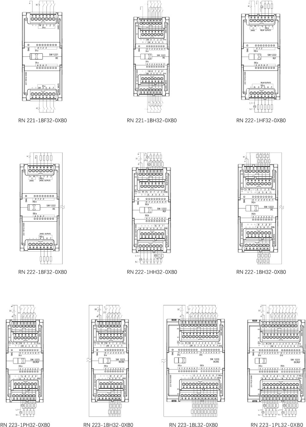
RN 1200 PLC Wiring Diagram
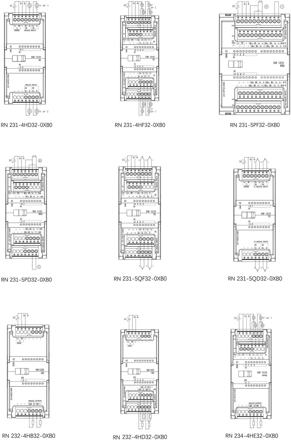
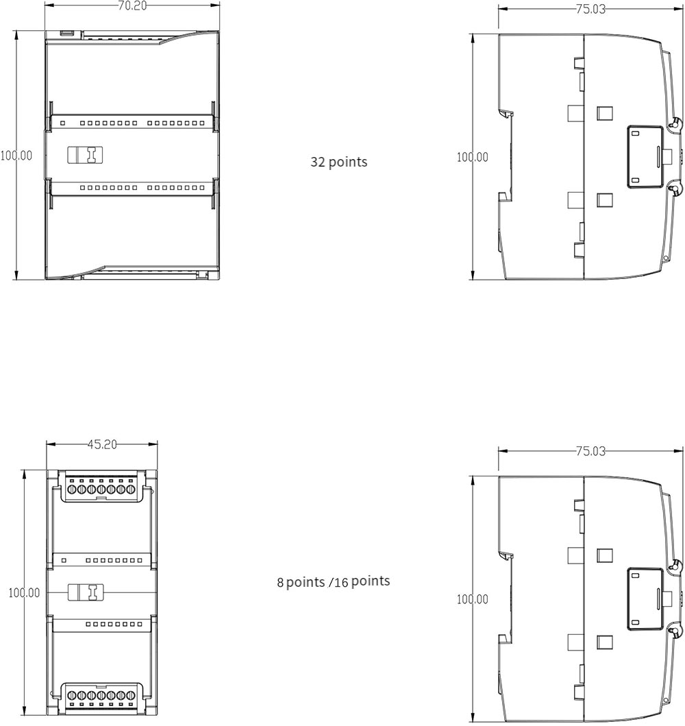
RN 1200 PLC Dimensional Drawing