English
 Español
 عربى
عربى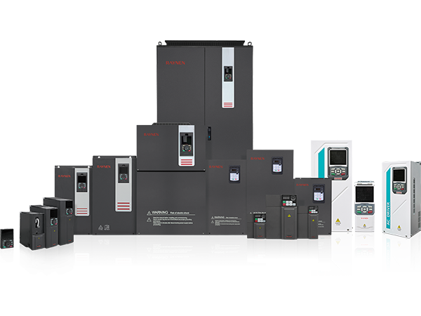


")
")


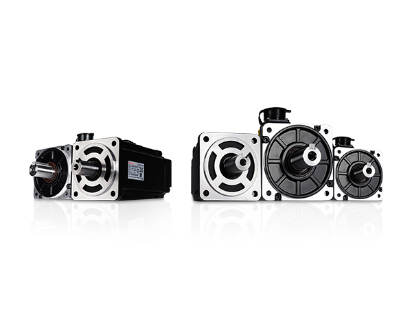
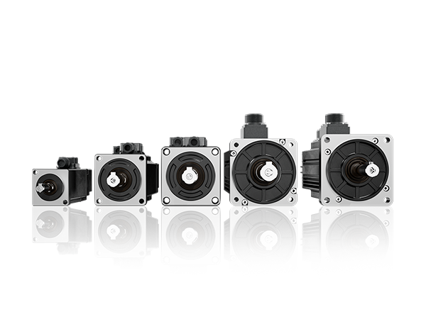
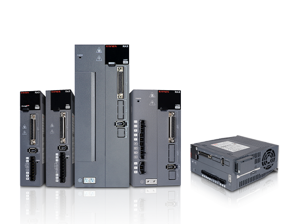
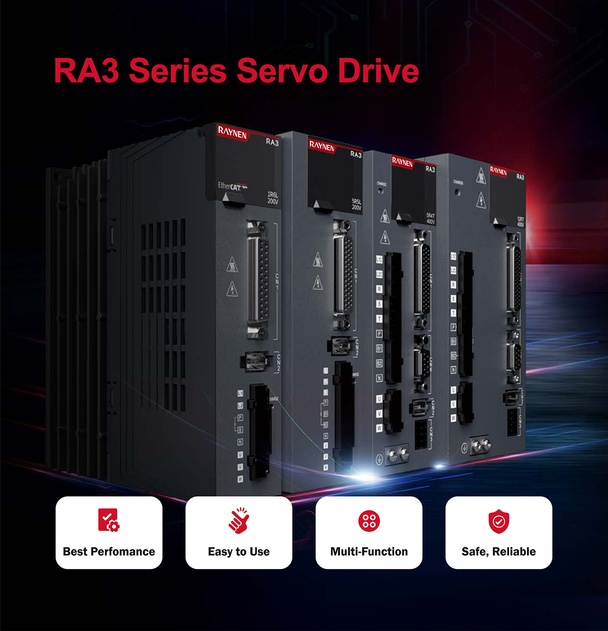
Product Summary
|
Power range from 100W to 7.5KW Supports pulse, analog, EtherCAT and CANopen |
|
|
Excellent performance Velocity response frequency up to 3.0kHz |
Accurate positioning Velocity ripple ±lrpm, torque ripple 0.5% |
|
Mult-function STO, all-full closed loop, high-speed I0, vibration suppression, notch filter, homing |
Ultra-high synchronization Multi-node signal fluctuation within +20ns, synchronization circle up to 250us |
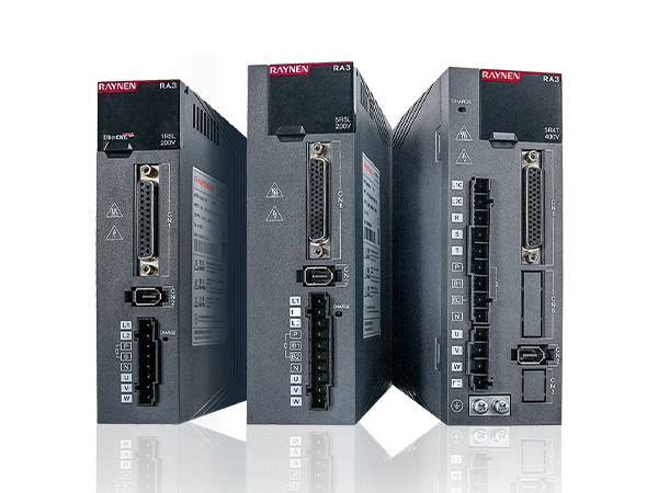
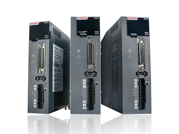
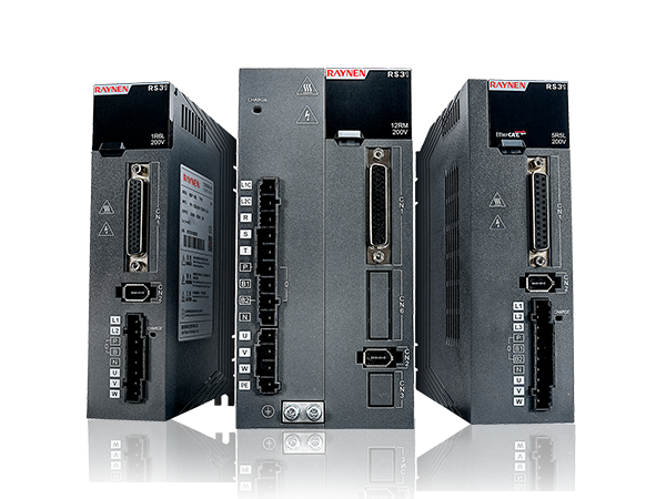
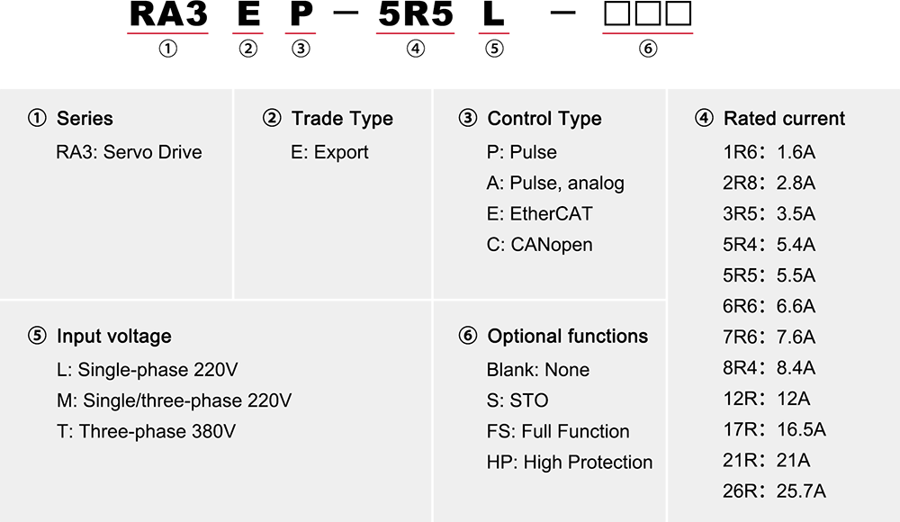
Model Nomenclature
Port Definition
|
|
|
|
|
|
|||||
|
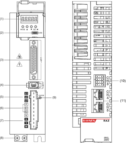
Size A |
Size B |
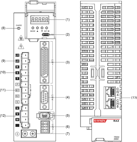
Size C |
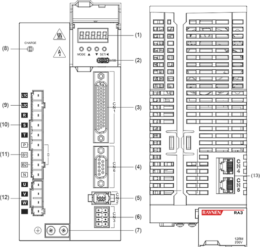
Size D |
Size E |
|||||
|
No. |
Name |
No. |
Name |
No. |
Name |
No. |
Name |
No. |
Name |
|
1 |
Digital tube display |
1 |
Digital tube display |
1 |
Digital tube display |
1 |
Digital tube display |
1 |
Digital tube display |
|
2 |
USB |
2 |
USB |
2 |
USB |
2 |
USB |
2 |
USB |
|
3 |
CN1 |
3 |
CN1 |
3 |
CN1 |
3 |
CN1 |
3 |
CN1 |
|
Fully closed loop encoder connector |
Fully closed loop encoder connector |
4 |
CN6 |
4 |
CN6 |
4 |
CN6 |
||
|
4 |
CN2 |
4 |
CN2 |
5 |
CN2 |
5 |
CN2 |
5 |
CN2 |
|
5 |
L1、L2 |
5 |
L1、L2、L3 |
6 |
CN3 |
6 |
CN3 |
6 |
CN3 |
|
6 |
P、B |
6 |
P、B1、B2 |
7 |
Ground screw |
7 |
Ground screw |
7 |
Ground screw |
|
P、N |
P、N |
8 |
CHARGE |
8 |
CHARGE |
8 |
CHARGE |
||
|
7 |
U、V、W |
7 |
U、V、W |
9 |
L1C、L2C |
9 |
L1C、L2C |
9 |
L1C、L2C |
|
8 |
Ground screw |
8 |
Ground screw |
10 |
R、S、T |
10 |
R、S、T |
10 |
R、S、T |
|
9 |
CHARGE |
9 |
CHARGE |
11 |
P、B1、B2 |
11 |
P、B1、B2 |
11 |
P、B1、B2 |
|
10 |
CN3 |
10 |
CN3 |
P、N |
P、N |
12 |
P、N1、N2 |
||
|
11 |
CN4/CN5 |
11 |
CN4/CN5 |
12 |
U、V、W、PE |
12 |
U、V、W、PE |
N1、N2 |
|
|
|
|
|
|
13 |
CN4/CN5 |
13 |
CN4/CN5 |
13 |
U、V、W |
|
|
|
|
|
|
|
|
|
14 |
CN4/CN5 |
|
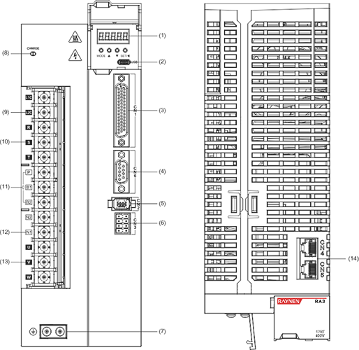
Description: ① Digital tube display: 5-digit 8-segment LED digital tube ②USB: USB Type-C interface, connected to PC ③CN1 (interface connector): output/input signal connection port, connected to programmable controller (PLC) or control I/O ④Fully closed-loop encoder connector: fully closed-loop interface, connected to external second encoder, '-FS' model supports this function ⑤CN2 (encoder connector): encoder interface, connected to the encoder on the servo motor ⑥L1, L2, L3 (main power input terminals): main circuit power supply, single-phase power supply is connected between L1 and L2 (200~240VAC, 50/60Hz power supply) ⑦L1C, L2C (control power input electronics): control circuit power supply, connected to single-phase power supply (200~240VAC or 380~440VAC, 50/60Hz power supply according to the model) ⑧R, S, T (main power input terminals ): Main circuit power supply, connect to three-phase power supply (200~240VAC or 380~440VAC, 50/60Hz power supply according to the model) ⑨P, B (external braking resistor connection terminal): use external braking resistor ⑩P, B1, B2 (external braking resistor connection terminal): use external braking resistor (remove the shorting piece between P and B1, connect to both ends of P and B2) ⑪P, N (N1, N2) (servo bus terminal): do not remove the shorting piece between N1 and N2, connect between P and N (N1) for multiple servos to share the DC bus ⑫N1, N2: connect external DC reactor (remove the shorting piece), short-circuit when not in use ⑬U, V, W, PE (servo motor connection terminal): servo drive output, connected to the motor power connector (U, V, W, PE) ⑭ Grounding screw: Connect to the power ground and motor ground ⑮CHARGE (bus voltage indicator): power indicator ⑰CN3 (connector for safety function): STO interface, only '-S/FS' models support this function ⑱CN4/CN5 (communication terminal): 485 communication port, EtherCAT high-speed communication port, CAN communication port |
|||||||||

Electrical specifications
|
Single-phase / three-phase 220V drive electrical specifications |
||||||||||||
|
Item |
Size A |
Size B |
Size C |
Size D |
Size C |
Size D |
Size E |
|||||
|
Model |
1R6L |
2R8L |
5R5L |
5R6L |
7R6M* |
12RM* |
7R6M |
12RM |
18RN |
22RN |
27RN |
|
|
Power supply capacity [kVA] |
0.5 |
1 |
1.7 |
2 |
2.3 |
4.2 |
2.3 |
4.2 |
6.9 |
8.4 |
10.3 |
|
|
Continuous output current [Arms] |
1.6 |
2.8 |
5.5 |
6.6 |
7.6 |
12 |
7.6 |
12 |
18 |
22 |
27 |
|
|
Instantaneous maximum output current [Arms] |
5.9 |
10.1 |
16.9 |
17 |
23 |
32 |
233 |
32 |
45 |
55 |
67.5 |
|
|
Main circuit |
Continuous input current [Arms] |
2.3 |
4 |
7.9 |
9.4 |
10.5 |
19.1 |
5.1 |
8.1 |
15 |
18 |
22 |
|
Main circuit power supply |
Single phase 200~240VAC, -10%~+10%, 50/60Hz |
Three-phase 200~240VAC, -10%~+10%, 50/60Hz |
||||||||||
|
Control loop |
Control circuit power supply |
Busbar power supply, shared power supply input and rectification |
Single phase 200~240VAC, -10%~+10%, 50/60Hz |
|||||||||
|
Power loss |
Main circuit power loss [W] |
30.5 |
41 |
60.8 |
63 |
42.9 |
83.3 |
42.9 |
83.3 |
170 |
208 |
278 |
|
Control circuit power loss [W] |
22 |
25 |
22 |
25 |
27 |
27 |
27 |
|||||
|
Braking resistor |
Brake resistor function |
No built-in support |
Standard built-in |
|||||||||
|
Resistance value [Ω] |
- |
- |
50 |
50 |
25 |
25 |
25 |
25 |
20 |
20 |
20 |
|
|
Capacity [W] |
- |
- |
50 |
50 |
80 |
80 |
80 |
80 |
100 |
100 |
100 |
|
|
External minimum allowable resistance value [Ω] |
50 |
45 |
40 |
40 |
20 |
15 |
20 |
15 |
15 |
15 |
15 |
|
|
Maximum braking energy that the capacitor can absorb [J] |
10.03 |
20.06 |
28.57 |
28.57 |
41.34 |
60.8 |
41.34 |
60.8 |
99.7 |
121.6 |
121.6 |
|
|
Cooling method |
Natural cooling |
Air Cooling |
||||||||||
|
Overvoltage level |
OVC III |
|||||||||||
*7R6M and 12RM recommend three-phase 220V input for better performance
|
Three-phase 380V drive electrical specifications |
||||||||
|
Item |
Size C |
Size D |
Size E |
|||||
|
Model |
3R5T |
5R4T |
8R4T |
12RT |
17RT |
21RT |
26RT |
|
|
Power supply capacity [kVA] |
2.3 |
3.5 |
4.5 |
6.2 |
8.1 |
11 |
14.5 |
|
|
Continuous output current [Arms] |
3.5 |
5.4 |
8.4 |
12 |
16.5 |
21 |
25.7 |
|
|
Instantaneous maximum output current [Arms] |
11 |
14 |
20 |
29.75 |
41.25 |
52.12 |
64.25 |
|
|
Main circuit |
Continuous input current [Arms] |
3.4 |
4.5 |
6.6 |
9.3 |
12 |
16 |
21 |
|
Main circuit power supply |
Three-phase 380~440VAC, -10%~+10%, 50/60Hz |
|||||||
|
Control loop |
Control circuit power supply |
Single phase 380~440VAC, -10%~+10%, 50/60Hz |
||||||
|
Power loss |
Main circuit power loss [W] |
34.4 |
70.9 |
95 |
155 |
238 |
275 |
336 |
|
Control circuit power loss [W] |
22 |
22 |
25 |
25 |
27 |
27 |
27 |
|
|
Braking resistor |
Brake resistor function |
Standard built-in |
||||||
|
Resistance value [Ω] |
100 |
100 |
50 |
50 |
35 |
35 |
35 |
|
|
Capacity [W] |
80 |
80 |
80 |
80 |
100 |
100 |
100 |
|
|
External minimum allowable resistance value [Ω] |
80 |
60 |
45 |
40 |
35 |
25 |
25 |
|
|
Maximum braking energy that the capacitor can absorb [J] |
33.2 |
40.33 |
59.3 |
59.3 |
97.26 |
118.61 |
118.61 |
|
|
Cooling method |
Air Cooling |
|||||||
|
Overvoltage level |
OVC III |
|||||||
Product size
|
Size A |
|||||||||||||||||
|
|
|
||||||||||||||||
|
Size B |
|||||||||||||||||
|
|
|
||||||||||||||||
|
Size C |
|||||||||||||||||
|
|
|
||||||||||||||||
|
Size D |
|||||||||||||||||
|
|
|
||||||||||||||||
|
Size E |
|||||||||||||||||
|
|
|
||||||||||||||||


Wiring Diagram
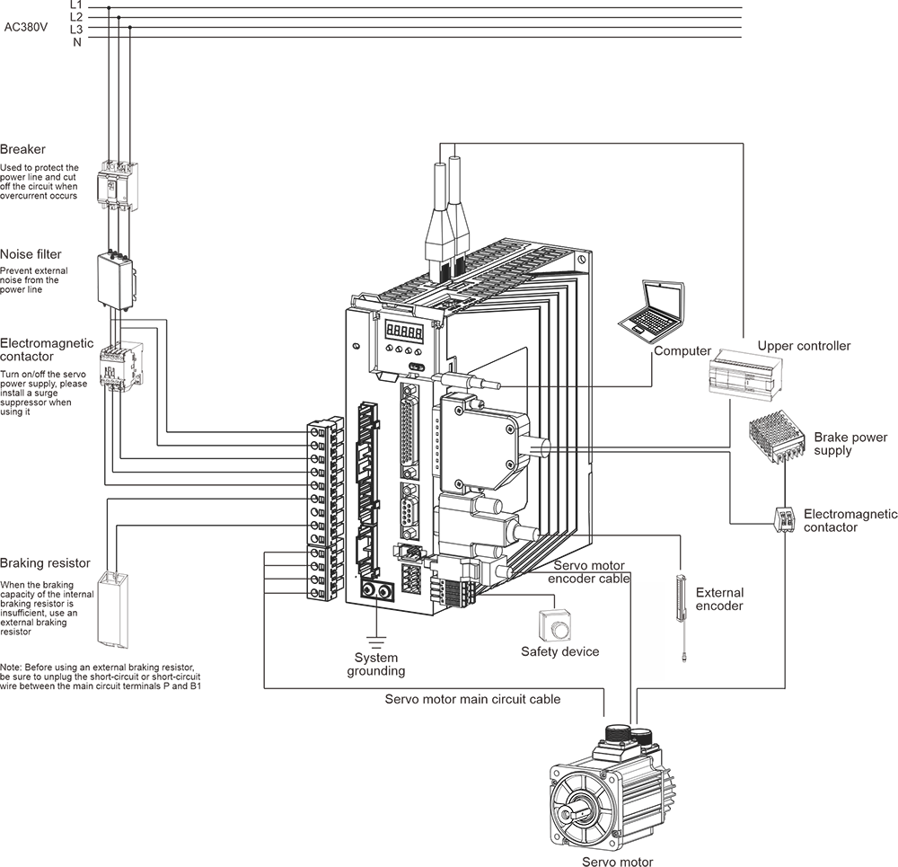
Note: The figure shows the wiring diagram of the RA3 series three-phase 380V Size C/D. For wiring diagrams of other models, please contact customer service.

-15(18)kW VFD")