English
 Español
 عربى
عربى
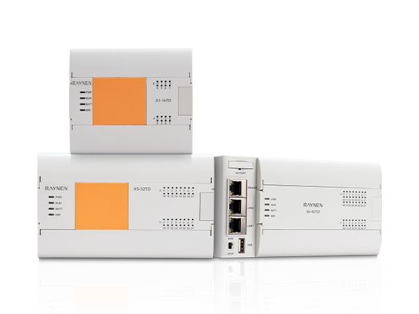
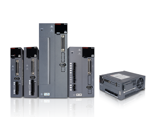


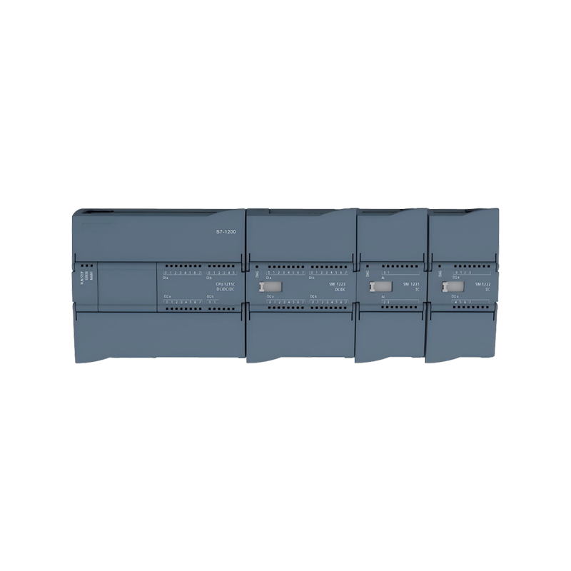
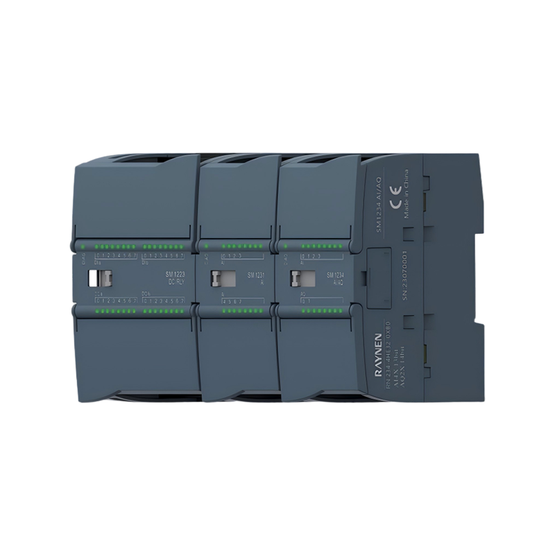
Extension Module
Technical Specification for Digital Input Module
|
Extension Module |
||
|
Technical Specification for Digital Input Module |
||
|
Model |
SM 1221 DI8×24 VDC |
SM 1221 DI16×24 VDC |
|
Order Number |
RN 221-1BF32-0XB0 |
RN 221-1BH32-0XB0 |
|
Routine |
||
|
Dimensions (W * H * D) |
45*100*75mm |
|
|
Power Consumption |
1.5W |
2.5W |
|
Current Consumption (Sm Bus) |
105mA |
130mA |
|
Current Consumption (24VDC) |
Input 4mA per point used |
|
|
Digital Input |
||
|
Input Points |
8 |
16 |
|
Input Type |
PNP/NPN |
|
|
Rated Voltage |
24 VDC,4mA |
|
|
Maximum Continuous Allowable Voltage |
30 VDC |
|
|
Surge Voltage |
35 VDC,0.5s |
|
|
Logic 1 [minimum] |
At 15 VDC, 2.5mA |
|
|
Logic 0 [maximum] |
1mA at 5 VDC |
|
|
Isolation Group |
2 |
4 |
|
Filtering Time |
0.2、0.4、0.8、1.6、3.2、6.4、12.8ms |
|
|
Simultaneously Connect Input Numbers |
8 |
16 |
|
Isolation (On-Site and Logical Side) |
707 VDC (type test) |
|
|
Cable Length (Maximum) |
500 meters (shielded), 300 meters (unshielded) |
|
|
Model |
SM 1222 DQ8X RLY |
SM 1222 DQ16X RLY |
SM 1222 DQ 8X24 VDC |
SM 1222 DQ 16X24 VDC |
|
Order Number |
RN 222-1HF32-0XB0 |
RN 222-1HH32-0XB0 |
RN 222-1BF32-0XB0 |
RN 222-1BH32-0XB0 |
|
Routine |
||||
|
Dimensions (W * H * D) |
45*100*75mm |
|||
|
Power Consumption |
3W |
4.5W |
1.5W |
2.5W |
|
Current Consumption (Sm Bus) |
120mA |
135mA |
120mA |
140mA |
|
Current Consumption (24vdc) |
Each relay coil used has 7mA |
50mA |
100mA |
|
|
Digital Output |
||||
|
Number of Output Points for Digital Quantity |
8 Relay outputs |
16 Relay outputs |
8-transistor output |
16-transistor output |
|
Output Type |
Dry contacts, relays |
Dry contacts, relays |
Solid state MOSFET, source type |
Solid state MOSFET, source type |
|
Voltage Range |
5~30 VDC or 5~250 VAC |
20.4~28.8V |
20.4~28.8V |
|
|
Logic 1 Signal at Maximum Current |
- |
- |
Minimum 20V |
Minimum 20V |
|
Logic 0 Signal with 10k ω Load |
- |
Maximum 0.1V |
Maximum 0.1V |
|
|
Current (Maximum) |
2A |
2A |
0.5A |
0.5A |
|
Lamp Load [maximum] |
30W DC/200W AC |
30W DC/200W AC |
5W |
5W |
|
On State Contact Resistance |
The maximum resistance of the new device is 0.2 Ω |
The maximum resistance of the new device is 0.2 Ω |
Maximum 0.6Ω |
Maximum 0.6Ω |
|
Leakage Current at Each Point |
- |
1 |
Maximum 10 μ A |
Maximum 10 μ A |
|
Inrush Current |
7A when the contact is closed |
7A when the contact is closed |
8A, Maximum duration of 100ms |
8A, Maximum duration of 100ms |
|
Overload Protection |
Nothing |
Nothing |
Nothing |
Nothing |
|
Isolation (On-Site and Logical Side) |
1500 VAC (coil and contacts) None (coil and logic side) |
707 VDC(Type testing) |
707 VDC(Type testing) |
|
|
Isolation Group |
2 |
4 |
1 |
1 |
|
Current at Each Common Terminal (Maximum) |
10A |
10A |
4A |
8A |
|
Inductive Clamp Voltage |
- |
L+-48V, 1W loss |
L+-48V, 1W loss |
|
|
Switch Delay |
Maximum 10ms |
Maximum 10ms |
The maximum duration from disconnection to connection is 50us/from connection to disconnection is 200us |
|
|
Mechanical Life Cycle |
10000000 open/close cycles |
|||
|
Contact Life Under Rated Load |
100000 open/close cycles |
|||
|
Behavior During Run-Stop |
Previous value or replacement value (default value is 0) |
|||
|
Number of Outputs Connected Simultaneously |
8 |
16 |
8 |
16 |
|
Cable Length (Maximum) |
500 meters (shielding); 150 meters (unshielded) |
|||
|
Model |
SM 1223 DI8×24 VDC DQ 8×RLY |
SM 1223 DI16×24 VDC DQ 16×RLY |
SM 1223 DI8×24 VDC DQ 8×24VDC |
SM 1223 DI16×24 VDC DQ 16×24VDC |
|
Order Number |
RN 223-1PH32-0XB0 |
RN 223-1PL32-0XB0 |
RN 223-1BH32-0XB0 |
RN 223-1BL32-0XB0 |
|
Routine |
||||
|
Dimensions (W * H * D) |
45*100*75mm |
70*100*75mm |
45*100*75mm |
70*100*75mm |
|
Power Consumption |
5.5W |
10W |
2.5W |
4.5W |
|
Current Consumption (Sm Bus) |
145mA |
180mA |
145mA |
185mA |
|
Current Consumption (24vdc) |
Each point used inputs 4mA/each relay coil used 7mA |
150mA |
200mA |
|
|
Digital Input |
||||
|
Input Points |
8 |
16 |
8 |
16 |
|
Input Type |
Leakage type/source type (IEC1 leakage type) |
Logic 1 signal (minimum) |
15 VDC at 2.5 mA |
|
|
Rated Voltage |
24 VDC at 4 mA, rated value |
Logic 0 signal (maximum) |
1 mA 时 5 VDC |
|
|
Allowable Continuous Voltage |
Maximum 30 VDC |
Isolation (on-site and logical side) |
707 VDC (type test) |
|
|
Surge Voltage |
35 VDC, Continuous for 0.5 seconds |
|||
|
Cable Length (Maximum) |
500 meters (shielded), 300 meters (unshielded) |
|||
|
Number of Inputs Connected Simultaneously |
8 |
16 |
8 |
16 |
|
Filtering Time |
0.2, 0.4, 0.8, 1.6, 3.2, 6.4, and 12.8ms (optional, 4 in a group) |
|||
|
Digital Output |
||||
|
Output Points |
8 |
16 |
8 |
16 |
|
Output Type |
Dry contacts, relays |
Dry contacts, relays |
Solid state MOSFET, source type |
Solid state MOSFET, source type |
|
Voltage Range |
5~30VDC or 5~250VAC |
20.4~28.8V |
20.4~28.8V |
|
|
Logic 1 Signal at Maximum Current |
- |
- |
Minimum 20 VDC |
Minimum 20 VDC |
|
Logic 0 Signal with 10k ω Load |
- |
- |
Maximum 0.1 VDC |
Maximum 0.1 VDC |
|
Current (Maximum) |
2 A |
2 A |
0.5 A |
0.5 A |
|
Lamp Load |
30 W DC/200 W AC |
30 W DC/200 W AC |
5 W |
5 W |
|
On State Contact Resistance |
The maximum resistance of the new device is 0.2 Ω |
The maximum resistance of the new device is 0.2 Ω |
Maximum 0.6Ω |
Maximum 0.6Ω |
|
Leakage Current at Each Point |
- |
Maximum 10μA |
Maximum 10μA |
|
|
Inrush Current |
When the contact is closed, it is 7 A |
When the contact is closed, it is 7 A |
8A, Maximum duration of 100 ms |
8A, Maximum duration of 100 ms |
|
Overload Protection |
Nothing |
Nothing |
Nothing |
Nothing |
|
Isolation (On-Site and Logical Side) |
1500 VAC (coil and contacts) None (coil and logic side) |
707 VDC(Type testing) |
707 VDC(Type testing) |
|
|
Current at Each Common Terminal |
10A |
8A |
4A |
8A |
|
Inductive Clamp Voltage |
- |
L+-48 V, 1 W loss |
L+-48 V, 1 W loss |
|
|
Switch Delay |
Maximum 10 ms |
Maximum 10 ms |
The maximum duration from disconnection to disconnection is 50 μ s/200 μ s |
|
|
Mechanical Lifespan (No Load) |
10000000 open/close cycles |
- |
- |
|
|
Contact Life Under Rated Load |
100000 open/close cycles |
- |
- |
|
|
Behavior of RUN-STOP |
Previous value or replacement value (default value is 0) |
|||
|
Number of Outputs Connected Simultaneously |
8 |
16 |
8 |
16 |
|
Cable Length (Maximum) |
500 meters (shielding); 150 meters (unshielded) |
|||
Technical Specification for Analog Input Module
|
Model |
SM 1231 AI 4X13 bit |
SM1231 AI8X13 bit |
|
Order Number |
RN 231-4HD32-0XBO |
RN 231-4HF32-0XBO |
|
Routine |
||
|
Dimensions (W * H * D) |
45*100*75mm |
|
|
Power Consumption |
2.2W |
2.3W |
|
Current Consumption (Sm Bus) |
80 mA |
90 mA |
|
Current Consumption (24vdc) |
45 mA |
45 mA |
|
Analog Input |
||
|
Number of Input Channels |
4 |
8 |
|
Type |
Voltage or current (differential): 2 can be selected as a group |
|
|
Scope |
± 10V, ± 5V, ± 2.5V, 0-20 mA or 4-20 mA |
|
|
Full Range (Data Words) |
-27648-27648, voltage; 0~27648, current |
|
|
Overrush/Downrush Range (Data Word) |
Voltage: 32511~27649/-27649~-32512 Current: 32511~27649/0~-4864 |
|
|
Overflow/Underflow Range (Data Words) |
Voltage: 32767~32512/-32513~-32768 Current 0-20 mA: 32767~32512/-4865~-32768 Current 4-20mA: 32767-32512/value less than -4864 indicates an open circuit |
|
|
Precision |
12 bits+symbol bit |
|
|
Maximum Voltage/Current Resistance |
±35V/±40 mA |
|
|
Smooth |
None, weak, moderate, or strong |
|
|
Noise Suppression |
400, 60, 50 or 10 Hz |
|
|
Impedance |
≥ 9 M Ω (voltage)/≥ 270 Ω,<290 Ω (current) |
|
|
Accuracy (25 ℃/0-55 ℃) |
± 0.1%/± 0.2% of full range |
|
|
Common-Mode Rejection |
40 dB,DC-60Hz |
|
|
Working Signal Range |
The signal plus common mode voltage must be less than +12V and greater than-12V |
|
|
Cable Length (Maximum) |
100 meters, shielded twisted pair cable |
|
|
Isolation (on-site side and logic side/logic side and 24 VDC/on-site side and 24 VDC/channel and channel) None |
||
|
Diagnosis |
||
|
Overflow/Underflow |
√ 1 |
|
|
Short Circuit to Ground (Voltage Mode Only) |
Not applicable |
|
|
Open Circuit (Current Mode Only) |
Only within the range of 4-20 mA (if the input is below -4864; 1.185 mA) |
|
|
24VDC Low Voltage |
√ |
|
Technical Specification for Analog Output Module
|
Model |
SM 1232 AQ 2X14 bit |
SM 1232 AQ 4X14 bit |
|
Order Number |
RN 232-4HB32-0XB0 |
RN 232-4HD32-0XB0 |
|
Routine |
||
|
Dimensions (W * H * D) |
45*100*75mm |
|
|
Power consumption |
1.8W |
2W |
|
Current consumption (SM bus) |
80 mA |
|
|
Current consumption (24VDC) |
45 mA (no load) |
|
|
Analog Output |
||
|
Output Path |
2 |
4 |
|
Type |
Voltage or current |
|
|
Scope |
± 10V, 0-20 mA or 4-20 mA |
|
|
Resolution |
Voltage: 14 bits; Current: 13 bits |
|
|
Full range (data words) |
Voltage: -276648~27648; Current: 0-27648 |
|
|
Accuracy (25 ℃/0-55 ℃) |
± 0.3%/± 0.6% of full range |
|
|
Stabilization time (95% of new value) |
Voltage: 300 μ s (R), 750 μ s (1uF); Current: 600 μ s (1mH), 2ms (10 mH) |
|
|
Load impedance |
Voltage: ≥ 1000 Ω; Current: ≤ 600 Ω |
|
|
Behavior of R U N - S T O P |
Previous value or replacement value (default value is 0) |
|
|
Isolation (on-site and logical side) |
Nothing |
|
|
Cable length (maximum) |
100 meters, shielded twisted pair cable |
|
|
Diagnosis |
||
|
Overflow/underflow |
√ |
|
|
Short circuit to ground (voltage mode only) |
√ |
|
|
Open circuit (current mode only) |
√ |
|
|
24 VDC low voltage |
√ |
|
|
Model |
SM 1234 AI 4X13 bit AQ 2X14 bit |
|
Order Number |
RN 234-4HE32-0XB0 |
|
Routine |
|
|
Dimensions (W * H * D) |
45*100*75mm |
|
Power Consumption |
2.4W |
|
Current Consumption (Sm Bus) |
80 mA |
|
Current Consumption (24vdc) |
60 mA (no load) |
|
Analog Input |
|
|
Number of Input Channels |
4 |
|
Type |
Voltage or current (differential): 2 can be selected as a group |
|
Scope |
± 10 V, ± 5V, ± 2.5 V, 0-20 mA or 4-20 mA |
|
Full Range (Data Words) |
-27,648~27,648 |
|
Overrush/Downrush Range (Data Word) |
Voltage: 32511~27649/-27649~-32512 Current: 32511~27649/0~-4864 |
|
Overflow/Underflow Range (Data Words) |
Voltage: 32767~32512/-32513~-32768 Current: 32767~32512/-4865~-32768 |
|
Resolution |
12 bits+symbol bit |
|
Maximum Voltage/Current Resistance |
±35 V/±40mA |
|
Smooth |
None, weak, moderate, or strong |
|
Noise Suppression |
400, 60, 50 or 10 Hz |
|
Impedance |
≥ 9 M Ω (voltage)/≥ 270 Ω,<290 Ω (current) |
|
Isolation (On-Site and Logical Side) |
Nothing |
|
Accuracy (25 ℃/0-55 ℃) |
± 0.1%/± 0.2% of full range |
|
Analog to Digital Conversion Time |
625μs(400Hz suppression) |
|
Common-Mode Rejection |
40 dB,DC-60 Hz |
|
Working Signal Range |
The signal plus common mode voltage must be less than +12V and greater than -12V |
|
Cable Length (Maximum) |
100 meters, shielded twisted pair cable |
|
Model |
SM 1234 AI 4X13 bit AQ 2X14 bit |
|
Analog Output |
|
|
Output Path |
2 |
|
Type |
Voltage or current |
|
Scope |
± 10V, 0-20 mA or 4-20 mA |
|
Precision |
Voltage: 14 bits; Current: 13 bits |
|
Full Range (Data Words) |
Voltage: -276648~27648; Current: 0-27648 |
|
Accuracy (25 ℃/0-55 ℃) |
± 0.3%/± 0.6% of full range |
|
Stabilization Time (95% of New Value) |
Voltage: 300 μ s (R), 750 μ s (1 uF); Current: 600 μ s (1mH), 2ms (10 mH) |
|
Load Impedance |
Voltage: ≥ 1000 Ω; Current: ≤ 600 Ω |
|
Behavior During Run-Stop |
Previous value or replacement value (default value is 0) |
|
Isolation (On-Site and Logical Side) |
Nothing |
|
Cable Length (Maximum) |
100 meters, shielded twisted pair cable |
|
Diagnosis |
|
|
Overflow/Underflow |
√ |
|
Short Circuit to Ground (Voltage Mode Only) |
√ |
|
Open Circuit (Current Mode Only) |
√ |
|
24 VDC Low Voltage |
√ |
Technical Specification for Thermocouple Analog Input Module
|
Model |
SM 1231 AI 4X16 bit thermocouple |
SM 1231 AI 8X16 bit thermocouple |
|
Order Number |
RN 231-5QD32-0XB0 |
RN 231-5QF32-0XB0 |
|
Routine |
||
|
Dimensions (W * H * D) |
45*100*75mm |
|
|
Power Consumption |
1.5W |
|
|
Current Consumption (Sm Bus) |
80 mA |
|
|
Current Consumption (24VDC) |
40 mA |
|
|
Analog Input |
||
|
Number of Input Channels |
4 |
8 |
|
Type |
Thermocouple |
|
|
Scope |
J, K, T, R, S, B, N, Voltage range: +/-80mv |
|
|
Resolution |
0.1℃/0.1°F 15 bits+symbol bit |
|
|
Temperature |
±35V |
|
|
Resistance |
85 dB,10Hz/50Hz/60Hz/400Hz时 |
|
|
Maximum Withstand Voltage |
>120 dB at 120V AC |
|
|
Noise Suppression |
≥ 10 M Ω (voltage) |
|
|
isolation On-site and logical side On-site side and 24V DC side 24V DC side and logic side |
707V DC (box type test) |
|
|
Isolation between channels |
120V AC |
|
|
Repetitiveness |
±0.05%FS |
|
|
Measuring principle |
Points |
|
|
Cold end error |
±1.5℃ |
|
|
Cable length (maximum) |
100 meters, shielded twisted pair cable |
|
|
Cable resistance |
Maximum 100 Ω |
|
|
Diagnosis |
||
|
Overflow/underflow |
√ |
|
|
Open circuit |
√ |
|
|
24V DC low voltage |
√ |
|
|
Model |
SM 1231 AI 4X16 bit thermistor |
SM 1231 AI 8X16 bit thermistor |
|
Order Number |
RN 231-5PD32-0XB0 |
RN 231-5PF32-0XB0 |
|
Routine |
||
|
Dimensions (W * H * D) |
45*100*75mm |
70*100*75mm |
|
Power Consumption |
1.5W |
|
|
Current Consumption (Sm Bus) |
80 mA |
90 mA |
|
Current Consumption (24VDC) |
40 mA |
|
|
Analog Input |
||
|
Number of Input Channels |
4 |
8 |
|
Type |
RTD and resistor |
|
|
Scope |
Platinum (Pt), copper (Cu), nickel (Ni), LG Ni or resistance, climate type PT100 |
|
|
Resolution Temperature Resistor |
0.1℃/0.1°F 15 bits+symbol bit |
|
|
Maximum Withstand Voltage |
±35V |
|
|
Noise Suppression |
85 dB,10Hz/50Hz/60Hz/400Hz时 |
|
|
Common-Mode Rejection |
>120 dB |
|
|
Impedance |
≥ 10 M Ω (voltage) |
|
|
Isolation On-site and logical side On-site side and 24 V DC side 24V DC side and logic side |
707V DC (box type test) |
|
|
Isolation Between Channels |
Nothing |
|
|
Repetitiveness |
±0.05%FS |
|
|
Measuring Principle |
points |
|
|
Cold End Error |
±1.5℃ |
|
|
Cable Length (Maximum) |
100 meters, shielded twisted pair cable |
|
|
Cable Resistance |
20 Ω, 2.7 Ω, for 100 RTD |
|
|
Diagnosis |
||
|
Overflow/Underflow |
√ |
|
|
Open Circuit |
√ |
|
|
24V DC Low Voltage |
√ |
|
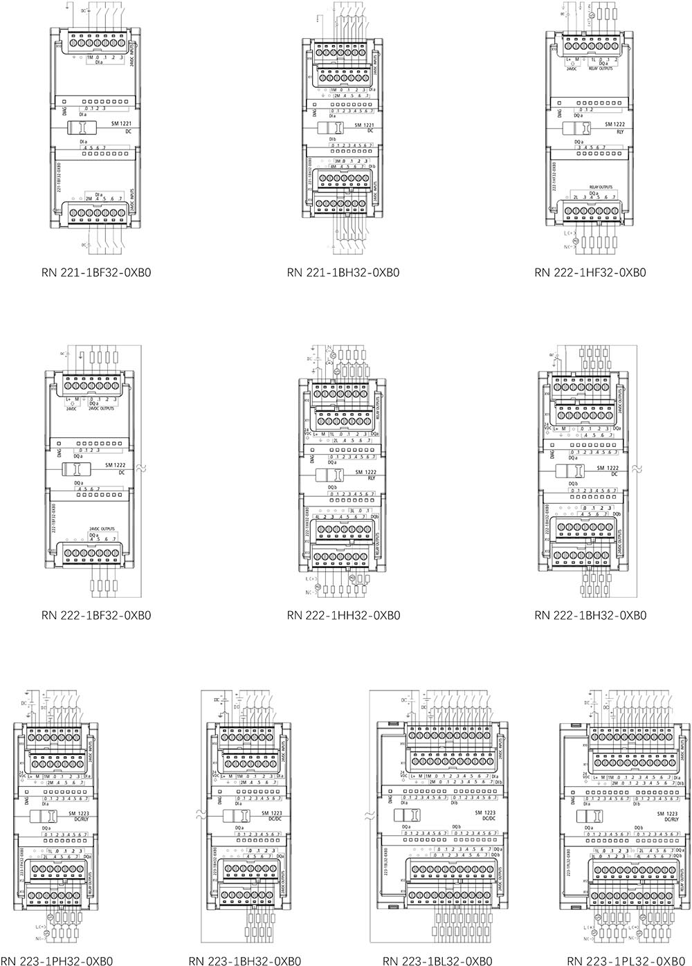
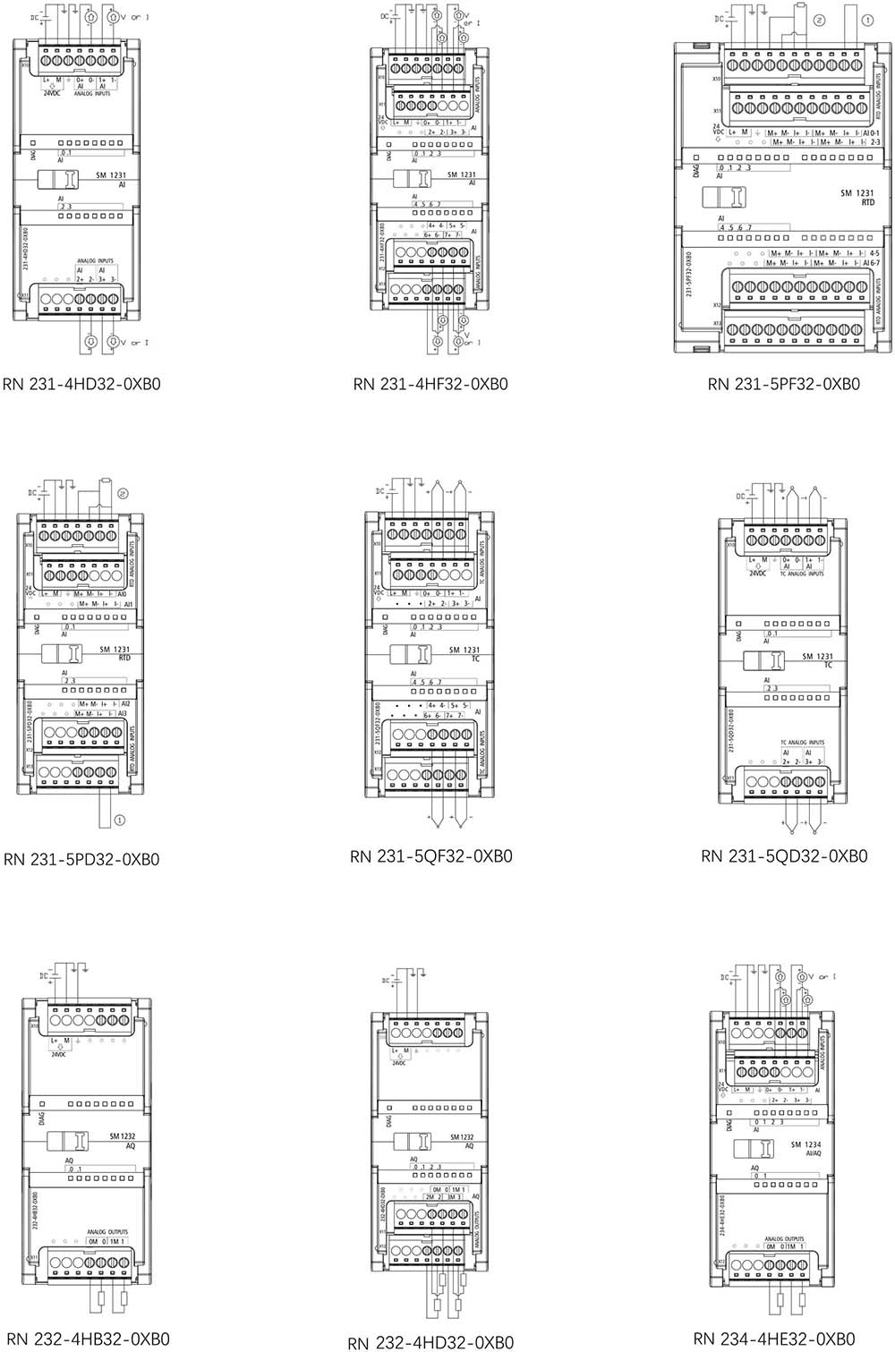
RN 1200 PLC Wiring Diagram
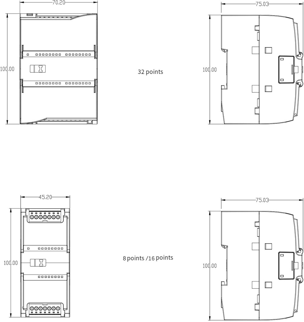
RN 1200 PLC Dimensional Drawing
-1.5(2.2)kW VFD")
kW VFD")