English
 Español
 عربى
عربى
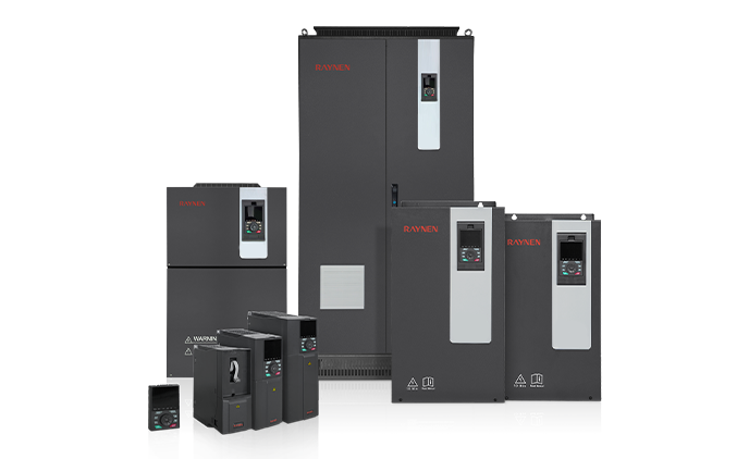
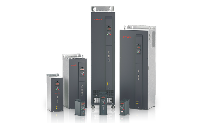
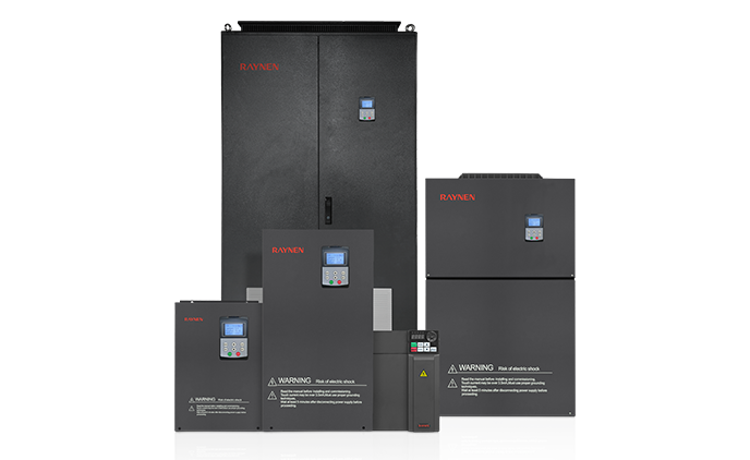
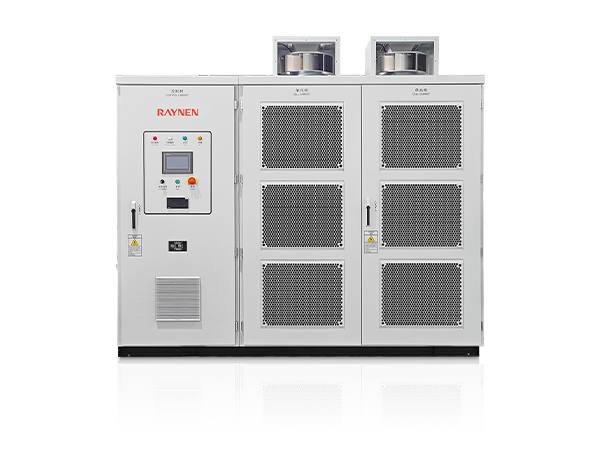
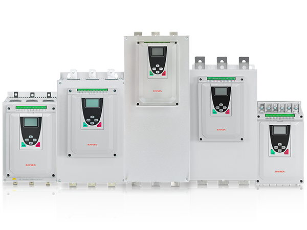
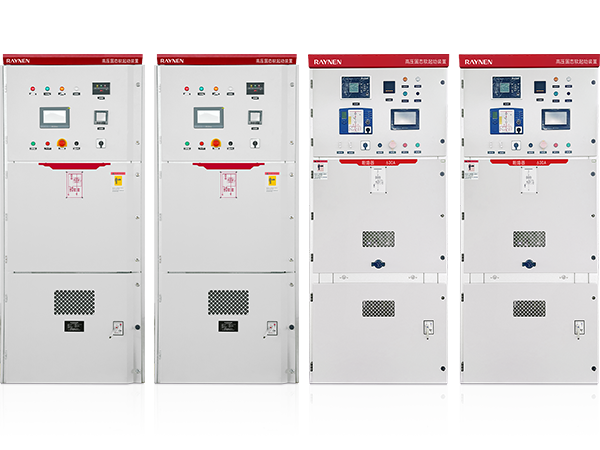
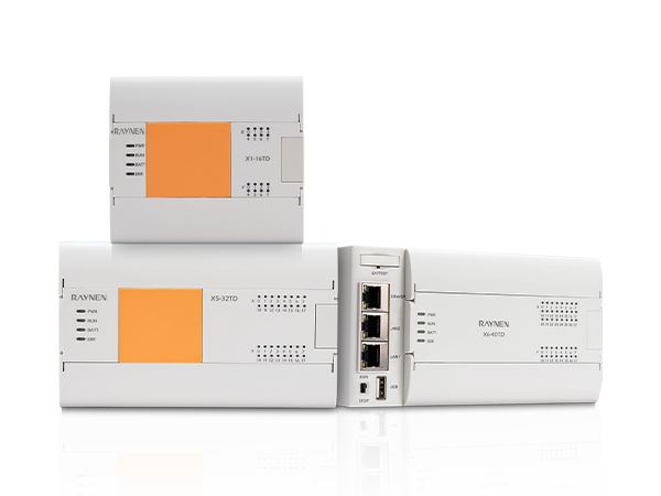
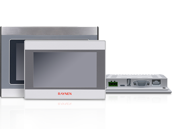
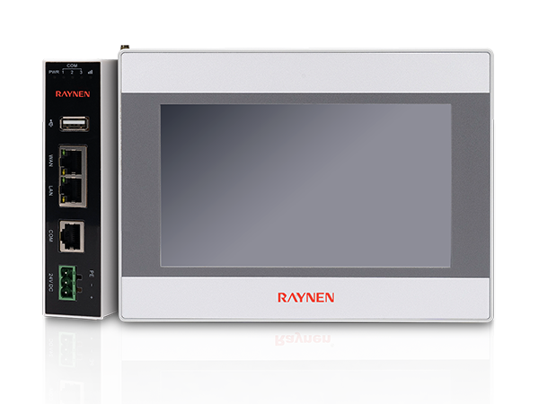
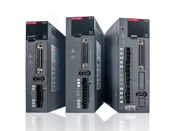
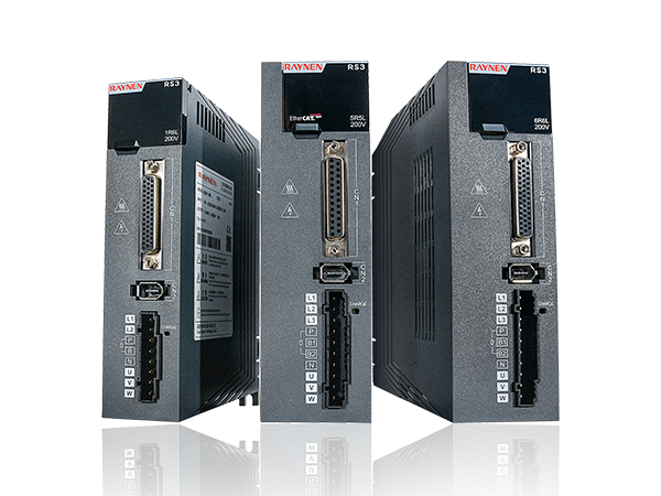
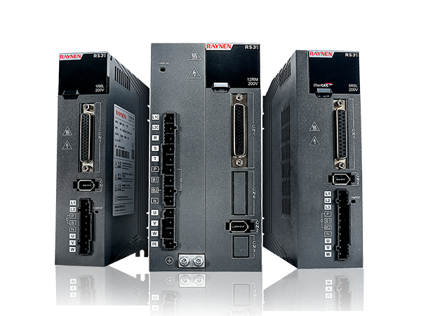










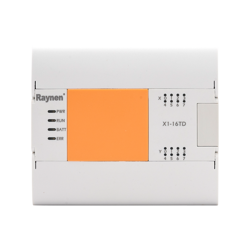
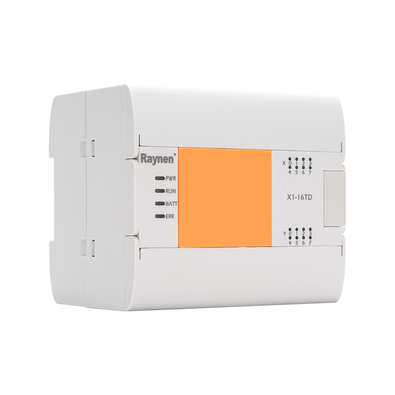
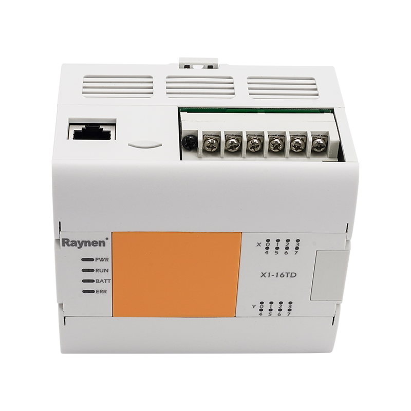
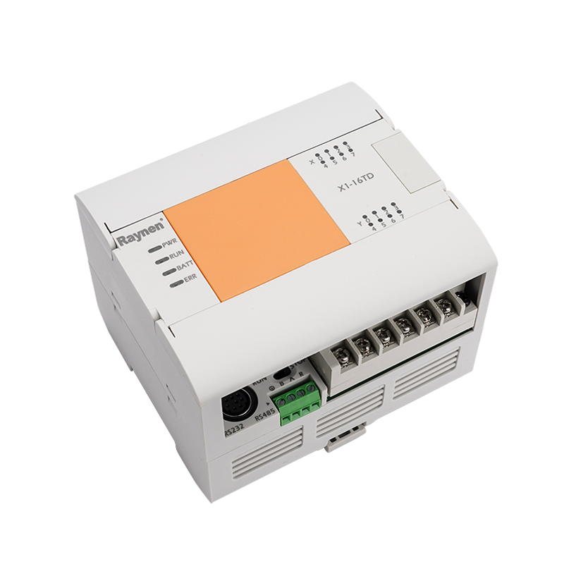
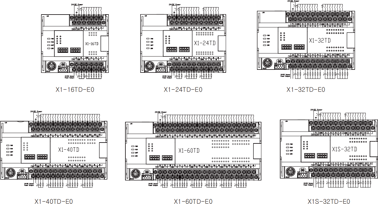
X series PLC is a powerful motion control functional PLC independently developed and designed. Including X1 economic PLC, X2 standard PLC, X3 enhanced PLC, X5 motion control PLC, X6 bus PLC, X relay PLC and expansion module, BD board. The X series PLC integrates the needs of the industry, responds to the individual needs of customers, enhances the advantages of expansion capabilities, and is the choice for control systems such as OEM equipment, small projects, and Internet of Things smart devices.
X1(S) series summary
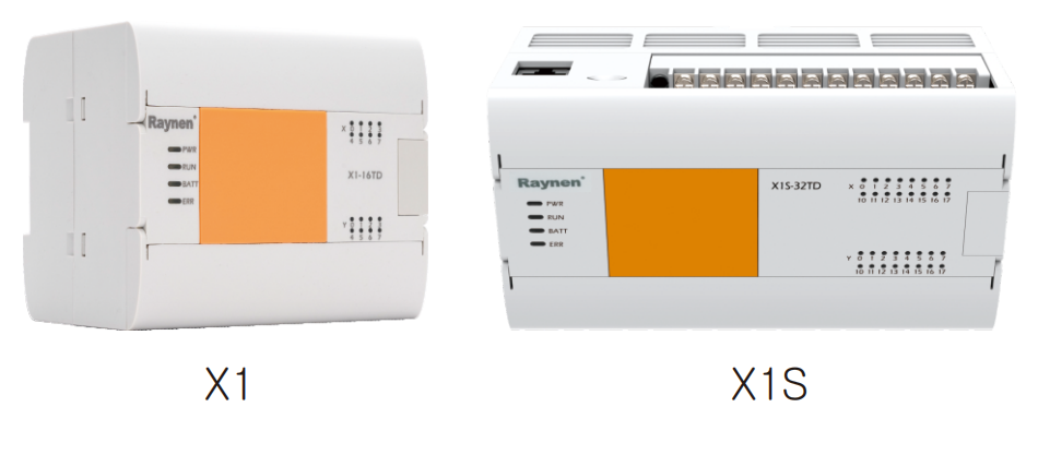
With pulse output, high-speed counting and other simple motion control functions;
Real-time clock, power outage data is permanently stored;
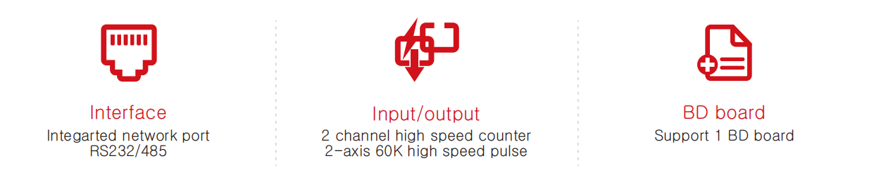
Supports one BD expansion board, but does not support template expansion.
Advantage
X1 series parameter
|
Item |
Power Specifications |
||||
|
X1-16TD |
X1-24TD |
X1-32TD |
X1-40TD |
X1-60TD |
|
|
X1S-16TD |
X1S-24TD |
X1S-32TD |
X1S-40TD |
X1S-60TD |
|
|
Power consumption |
6W |
7W |
8W |
9W |
11W |
|
Power supply voltage |
DC24V |
||||
|
Power supply voltage range |
DC20.4~28.8V |
||||
|
Permitted instantaneous power failure time |
For transient power outages below 5ms, the operation will continue |
||||
|
Power supply fuse |
60V 2A |
||||
|
Surge current |
12A, 0.5ms Below/28.8V DC |
||||
|
DC24V power supply |
Below 300mA |
||||
|
Working environment temperature |
-10℃~60℃(horizontal installation), -10℃~50℃(vertical installation) |
||||
|
Transportation environment temperature |
-20℃~80℃ |
||||
|
Ambient relative humidity |
5~95%, non-condensing(RH level 2, conform IEC61131-2) |
||||
|
Protection level |
IP20 |
||||
|
Electromagnetic compatibility |
Noise suppression, conform to EC61000-6-2 |
||||
|
Mechanical level (vibration) |
IEC60068, Part2-6/10up58Hz |
||||
|
Withstand voltage |
AC1.5KV 1 min, Between each terminal and the ground terminal |
||||
|
AC500V 1 min, Between each terminal and the ground terminal |
|||||
|
Insulation resistance |
After measuring with a DC500V insulation resistance meter, it is more than 5MΩ between each terminal and the ground terminal |
||||
|
Grounding |
Type D grounding(grounding resistance: less than 100Ω), do not allow common grounding with the strong current system |
||||
|
Usage environment |
No corrosive, flammable gas, conductive dust (dust)is not serious |
||||
|
Usage altitude |
2000M Below(Can not be used in the environment of pressure to above atmospheric pressure, otherwise it may occur) |
||||
|
Item |
Power Specifications |
|||||
|
X1-16TD |
X1-24TD |
X1-32TD |
X1-40TD |
X1-60TD |
||
|
X1S-16TD |
X1S-24TD |
X1S-32TD |
X1S-40TD |
X1S-60TD |
||
|
Input number |
8 |
14 |
16 |
24 |
36 |
|
|
High speed number |
signal phase 60KHz(2 way)AB phase 30KHz(1 way) |
|||||
|
Input connect type |
Removable terminal block(M3 screw) |
|||||
|
Input type |
Sink type/source Type |
|||||
|
Input signal voltage |
DC power: DC20.4V~28.8V |
|||||
|
Input impedance |
X0-X2 |
2.4K |
||||
|
X3 above |
5.6K |
|||||
|
ON input inductance current |
X0-X2 |
5mA above |
||||
|
X3 above |
2.4mA above |
|||||
|
OFF Input inductance current |
1mA below |
|||||
|
Input response time |
No more than 4.5ms |
|||||
|
Input signal form |
No voltage contact input |
|||||
|
Sink input: NPN open-collector transistor |
||||||
|
Input loop isolation |
Source input: PNP open-collector transistor |
|||||
|
Optocoupler isolation |
||||||
|
Display of input actions |
The LED on the panel lights up when the optocoupler is driven |
|||||
|
Item |
Power Specifications |
|||||
|
X1-16TD |
X1-24TD |
X1-32TD |
X1-40TD |
X1-60TD |
||
|
X1S-16TD |
X1S-24TD |
X1S-32TD |
X1S-40TD |
X1S-60TD |
||
|
Output number |
8 |
10 |
16 |
20 |
24 |
|
|
Pulse frequency(Max) |
Single terminal 2 shaft 60KHz |
|||||
|
Output connect type |
Removable terminal block(M3 Screw) |
|||||
|
Output type |
Transistor/drain output |
|||||
|
External power supply |
DC5~30V |
|||||
|
Max load |
Resistive load |
0.5A/single point; 0.8A/4 point |
||||
|
Inductive load |
12W/DC24V |
|||||
|
Lamp load |
High speed: 2W/DC24V, common: 5W/DC24V |
|||||
|
Mid load |
5mA(DC5~24V) |
|||||
|
Open leakage current |
0.1mA below/DC30V |
|||||
|
on-resistance |
High speed point 0.3Ω typical value(Max 0.6Ω) |
|||||
|
Response |
OFF→ON |
High speed: 10us below/10mA above(DC5~24V) |
||||
|
Common: 0.2ms below/200mAabove(DC24V) |
||||||
|
ON→OFF |
High speed: 10us below/10mA above(Dc5~24V) |
|||||
|
Common: 0.2msbelow/200mAabove(DC24V) |
||||||
|
Loop isolation |
Optocoupler isolation |
|||||
|
Display of output actions |
The LED on the panel lights up when the optocoupler is driven |
|||||
|
Mask transmission distance |
500M(common output) |
|||||
|
unmasked transmission distance |
150M(common output) |
|||||
X1 series: software component resources
|
Item |
Performance |
|||
|
Operational control mode |
Method of repeatedly executing saved programs(dedicated LSI)with interrupt function |
|||
|
Input/output control mode |
Batch processing mode(when executing END instruction), input and output refresh instruction, pulse capture function |
|||
|
Programming language |
Relay symbol mode +step ladder mode(can be represented by SFC) |
|||
|
Real-time clock |
Clock function |
Build-in 2000-2099, The annual error is not more than +5 minutes/25℃ |
||
|
Program memory |
Max memory capacity |
32000 step can be set by parameters, write comments and file registers in the program memory |
||
|
Built-in memory capacity/model |
32000 step/RAM memory, Password protected |
|||
|
Write function In RUN |
No |
|||
|
Instruction type |
Basic instruction |
27 types of Sequential control instructions, 2 types of step ladder diagram instructions |
||
|
Application instruction |
218 kinds 497 type |
|||
|
Arithmetic processing speed |
Basic command |
0.065μs/instruction |
||
|
Input/output number |
Number of input points for extended usage |
256 point |
Total input and output points do not exceed 256 points |
|
|
Number of output points for extended usage |
256 point |
|||
|
Input-output relay |
Input relay |
256 point |
Input and output total 256 points |
|
|
Output relay |
256 point |
|||
|
Auxiliary relay |
Common |
M0~M7679 |
7680 point |
Common/retention Settings can be changed through parameters |
|
Retention |
M500~M1023 |
524 point |
||
|
State |
Common |
S0~S4095 |
4096 point |
Common/retention Settings can be changed through parameters |
|
Retention |
S500~S999 |
500 point |
Common/retention Settings can be changed through parameters |
|
|
Timer |
100ms type |
T0~T199 |
200 point |
0.1~3276.7s |
|
10ms type |
T200~T245 |
46 point |
0.01~327.67s |
|
|
1ms Cumulative type |
T246~T249 |
4 point |
0.001~32.767S |
|
|
100ms Cumulative type |
T250~T255 |
6 point |
0.1~3276.7s |
|
|
1ms type |
T256~T511 |
256 point |
||
|
Counter |
General increasing |
C0~C99 |
100 point |
0.001~32.767s |
|
(16-bit)[Changeable] |
Common/retention Settings can be changed through parameters |
|||
|
Retention increasing(16 bit)[changeable] |
C100~C199 |
100 point |
||
|
Common duplexing |
C200~C219 |
20 point |
Common/retention Settings can be changed through parameters |
|
|
(32-bit)[Changeable] |
||||
|
Retention duplexing(32 bit) [changeable] |
C220~C255 |
36 point |
||
|
Data register |
Common |
D0~D7999 |
8000 point |
Common/retention Settings can be changed through parameters |
|
Retention |
D200~511 |
312 point |
||
|
Expansion register |
Main control |
P0~P1023 |
1024 point |
CJ command、CALL command used |
|
Ponter |
Main control |
NO~N7 |
8 point |
MC command used |
|
Nest |
Main control |
16 bit |
-32, 768~+32, 767 |
|
|
State |
10 Decimal Number(K) |
32 bit |
-2, 147, 483, 648~+2, 147, 483, 647 |
|
|
16 hexadecimal number(H) |
16 bit |
0~FFFF |
||
|
32 bit |
0~FFFFFFFF |
|||
|
Real number (E) |
32 bit |
-3.40×10⁻³8~-1.17×10⁻, 1.17×10⁻~3.40×10³8 |
||
|
Character string("") |
Character string |
Specify with characters in"I maximum of 32 half-corner characters can be used in a constant in an instruction |
||
X1 series high-speed counter
|
Distribution Input |
Single-phase single counter |
AB Phase counter |
|||||
|
C235 |
C236 |
C237 |
C243 |
C244 |
C251 |
C252 |
|
|
X0 |
U/D |
U/D |
A |
A |
|||
|
X1 |
U/D |
R |
B |
B |
|||
|
X2 |
U/D |
U/D |
R |
||||
|
X3 |
R |
||||||
X1 series size
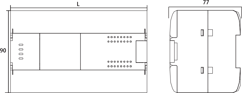
|
PLC model |
L |
|
X1-16TD-E0 |
104 |
|
X1-24TD-E0 |
132 |
|
X1-32TD-E0 |
150 |
|
X1-40TD-E0 |
165 |
|
X1-60TD-E0 |
210 |
|
X1S-32TD-E0 |
150 |
X1 series wire drawing