English
 Español
 عربى
عربى


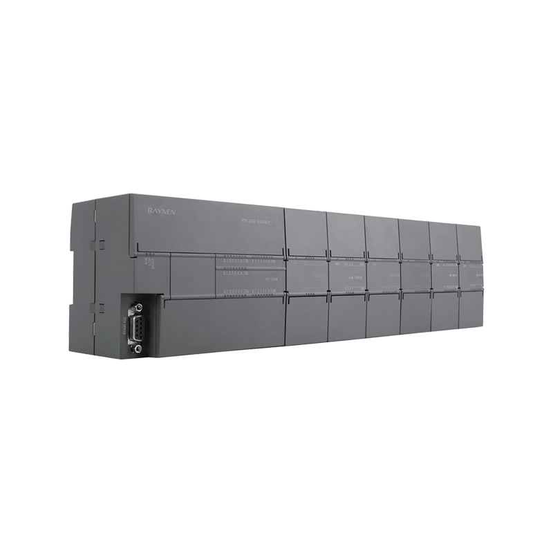
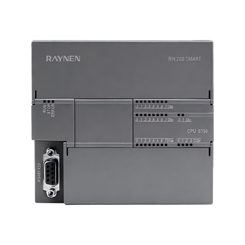


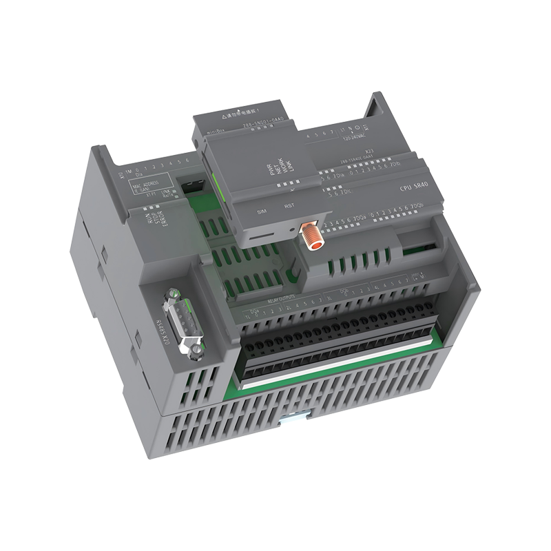
RN200 SMART FAMILY OF PRODUCTS
ALL MODELS ARE AVAILABLE, AND ALL FUNCTIONS ARE INCLUDED.

TRULY COMPATIBLE, REPLACE WITH CONFIDENCE
STANDARD CPU
|
MODEL |
CPU SR20 |
CPU ST20 |
|
|
Selected CPU |
RN288-1SR20-OABO |
RN288-1ST20-0ABO |
|
|
Dimensions(W x H x D)(mm) |
90×100×81 |
||
|
Power Input Voltage Range |
85~264V C |
20.4~28.8V DC |
|
|
Power Output Voltage Range |
20.4~28.8V DC /Rated output current(maximum)300mA |
||
|
Number Input Current Consumption |
4 mA per input point |
||
|
CPU FEATURES |
|||
|
User memory Onboard digital I/O Module expansion |
32KB Program Memory /12KB Data Memory /12KB Retention Memory 12 Inputs /8 Outputs Up to 6 Extended Modules |
||
|
Signal board expansion |
Up to 1 Signal Board |
||
|
High-speed counter |
Total 6/Single Phase:6 channels 200 kHz/AB Phase:4 channels 100 kHz |
||
|
High-speed pulse |
- |
2 channels 200 kHz |
|
|
COMMUNICATION |
|||
|
Number of terminals |
Ethernet:1 PGcommunication, 6 shared by OUC+PUT/GET+HMI /Serial Port:1(RS485)Extended Port:Optional RS485 BD board |
||
|
Programming device |
Serial Port:1 connection, Ethernet Port:1 connection |
||
|
CPU(PUT/GET) |
Ethernet: Total number of client and server connections:6 |
||
|
NUMBER INPUT |
|||
|
Number of input points |
12 |
||
|
Type |
Drain/Source |
||
|
Rated voltage |
Normal DI point:24 V DC at 4 mA, rated / |
||
|
Permissible continuous voltage |
High-speed DI point:24V DC at 6.5 mA, rated maximum 30V DC |
||
|
Logic 1 signal(minimum) |
0.0-I0.3, I0.6-I1.1:15V DC at 3.7 mA Others:15VDC at 2.5 mA |
I0.0-I0.3:4VDC at 12.75mA I0.6-I1.1:15VDC at 3.7mA Others:15VDC at 2.5mA |
|
|
Logic 0 signal(maximum) |
5V DC at 1 mA |
I0.0-I0.3:1VDC at 1mA Other inputs:5VDC at 1mA |
|
|
Filtering time |
Each channel can be individually selected(points 10.0 to 11.3) 0.2, 0.4, 0.8, 1.6, 3.2, 6.4 and 12.8μs/0.2, 0.4, 0.8, 1.6, 3.2, 6.4 and 12.8 ms |
||
|
DIGITAL OUTPUT |
|||
|
Number of output points |
8 |
||
|
Type |
Relay, contact |
Transistor |
|
|
Voltage range |
5~30 V DC /or 5~250 V AC |
20.4~28.8 V DC |
|
|
Rated current per point(maximum) |
2.0 A |
0.5 A |
|
|
MODEL |
CPU SR20XP |
CPU ST20XP |
||
|
Selected CPU |
RN 288-1SR20XP-0AB0 |
RN 288-1ST20XP-0ABO |
||
|
Dimensions(W x H x D)(mm) |
110×100x81 |
|||
|
Power Input Voltage Range |
85~264V AC |
20.4~28.8V DC |
||
|
Power Output Voltage Range |
20.4~28.8V DC/Rated output current(maximum)300mA |
|||
|
Number Input Current Consumption |
4 mA input per point |
|||
|
CPU FEATURES |
||||
|
User memory |
32KB Program Memory /12KB Data Memory /12KB Retention Memory |
|||
|
Onboard digital I/O |
12 Inputs /8 Outputs |
|||
|
Module expansion |
Up to 6 Extended Modules |
|||
|
Signal board expansion |
Up to 1 Signal Board |
|||
|
High-speed counter |
Total 6/Single Phase:6 channels 200 kHz/AB Phase:4 channels 100 kHz |
|||
|
High-speed pulse |
- |
2 channels 200 kHz |
||
|
COMMUNICATION |
||||
|
Number of terminals |
Ethernet:1 PGcommunication, 6 shared by OUC+PUT/GET+HMI /Serial Port:1(RS485)/Extended Port:Optional RS485 BD board |
|||
|
Programming device |
Serial Port:1 connection, Ethernet Port:1 connection |
|||
|
CPU(PUT/GET) |
Ethernet: Total number of client and server connections:6 |
|||
|
NUMBER INPUT |
||||
|
Number of input points |
12 |
|||
|
Type |
Drain/Source Type |
|||
|
Rated voltage |
Normal DI Point:24V DC at 4 mA, rated /High-Speed DI Point:24V DC at 6.5 mA, rated |
|||
|
Permitted continuous voltage |
Maximum 30 V DC |
|||
|
Logic 1 signal(minimum) |
II0.0-I0.3, I0.6-I1.1:15V DC at 3.7 mA Others:15V DC at 2.5 mA |
I0.0-I0.3:4VDC at 12.75mA I0.6-I1.1:15VDC at 3.7mA Others:15VDC at 2.5mA |
||
|
Logic 0 signal(maximum) |
5V DC at 1 mA |
I0.0-I0.3:1VDC at 1mA Other inputs:5VDC at 1mA |
||
|
Filtering time |
Each channel can be individually selected(points 10.0 to 11.3): 0.2, 0.4, 0.8, 1.6, 3.2, 6.4, and 12.8μs /0.2, 0.4, 0.8, 1.6, 3.2, 6.4, and 12.8 ms |
|||
|
DIGITAL OUTPUT |
||||
|
Number of output points |
8 |
|||
|
Type |
Relay, contact |
transistor |
||
|
Voltage range |
5~30V DC /or 5~250V AC |
20.4~28.8 V DC |
||
|
Rated current per point(maximum) |
2.0 A |
0.5 A |
||
|
ANALOG INPUT |
ANALOG OUTPUT |
|||
|
Number of Input Points |
4 |
Number of output points |
2 |
|
|
Type |
single-ended |
Output type |
voltage or current |
|
|
Voltage Input Range |
±10V |
Voltage output range |
0~10V |
|
|
Current Input Range |
0~20mA |
Current output range |
0~20mA |
|
|
Voltage Data Range |
-27648~+27648 |
Resolution |
12 digits |
|
|
Current Data Range |
0~27648 |
Data range |
Voltage:0~27648/Current:0~27648 |
|
|
Analog Input Address |
AIWO-AIW6 AQW0-AQW2 |
|||
|
MODEL |
CPU SR30 |
CPU ST30 |
|
Selected CPU |
RN288-1SR30-0ABO |
RN 288-1ST30-0ABO |
|
Dimensions(WxHx D)(mm) |
110×100×81 |
|
|
Power Input Voltage Range |
85~264V AC |
20.4~28.8V DC |
|
Power Output Voltage Range |
20.4~28.8V DC /Rated output current(maximum)300mA |
|
|
Number Input Current Consumption |
4 mA per input point |
|
|
CPU FEATURES |
||
|
User memory |
32KB Program Memory /16KB Data Memory /12KB Retention Memory |
|
|
Onboard digital I/O |
18 Inputs /12 Outputs |
|
|
Module expansion |
Up to 6 Extended Modules |
|
|
Signal board expansion |
Up to 1 Signal Board |
|
|
High-speed counter |
Total 6 /Single Phase:6 channels 200 kHz /AB Phase:4 channels 100 kHz |
|
|
High-speed pulse |
- |
3 channels 200 kHz |
|
COMMUNICATION |
||
|
Number of terminals |
Ethernet:1 PGcommunication, 6 shared by OUC+PUT/GET+HMI /Serial Port:1(RS485/Extended Port:Optional RS485 BD board |
|
|
Programming device |
Serial Port:1 connection, Ethernet Port:1 connection |
|
|
CPU(PUT/GET) |
Ethernet: Total number of client and server connections:6 |
|
|
NUMBER INPUT |
||
|
Number of Input Points |
18 |
|
|
Type |
Drain/Source Type |
|
|
Rated Voltage |
Normal DI Point:24V DC at 4 mA, rated /High-Speed DI Point:24V DC at 6.5 mA, rated |
|
|
Permitted Continuous Voltage |
IMaximum 30V DC |
|
|
Logic 1 Signal(Minimum) |
I0.0-I0.3, I0.6-I1.1:15 V DC at 3.7 mA Others:15V DC at 2.5 mA |
I0.0-I0.3:4VDC at 12.75mA I0.6-I1.1:15VDC at 3.7mA Others:15VDC at 2.5mA |
|
Logic O Signal(Maximum) |
5V DC at 1 mA |
I0.0-I0.3:1VDC at 1mA Other inputs:5VDC at 1mA |
|
Filtering Time |
Individually selectable for each channel (points 10.0 to 11.5) 0.2, 0.4, 0.8, 1.6, 3.2, 6.4, and 12.8μs/0.2, 0.4, 0.8, 1.6, 3.2, 6.4, and 12.8ms Individually selectable for each channel(1.6 and larger points):0, 6.4, 12.8 ms |
|
|
DIGITAL OUTPUT |
||
|
Number of output points |
12 |
|
|
Type |
Relay, contact |
Transistor |
|
Voltage range |
5~30V DC /or 5~250V AC |
20.4~28.8 V DC |
|
Rated current per point(maximum) |
2.0 A |
0.5 A |
|
MODEL |
CPU SR40 |
CPU ST40 |
|
Selected CPU |
RN 288-1SR40-0ABO |
RN 288-1ST40-0ABO |
|
Dimensions(W x H x D)(mm) |
125x100x81 |
|
|
Power Input Voltage Range |
85~264V AC |
20.4~28.8V DC |
|
Power Output Voltage Range |
20.4~28.8V DC /Rated output current(maximum)300mA |
|
|
Number Input Current Consumption |
4 mA per input point |
|
|
CPU FEATURES |
||
|
User memory |
32KB Program Memory /20KB Data Memory /12KB Retention Memory |
|
|
Onboard digital I/O |
24 Inputs /16 Outputs |
|
|
Module expansion |
Up to 6 Extended Modules |
|
|
Signal board expansion |
Up to 1 Signal Board |
|
|
High-speed counter |
Total 6 /Single Phase:6 channels 200 kHz/AB Phase:4 channels 100 kHz |
|
|
High-speed pulse |
- |
3 channels 200 kHz |
|
COMMUNICATION |
||
|
Number of terminals |
Ethernet:1 PGcommunication, 6 shared by OUC+PUT/GET+HMI/Serial Port:1(RS485)/Extended Port:Optional RS485 BD board |
|
|
Programming device |
Serial Port:1 connection, Ethernet Port:1 connection |
|
|
CPU(PUT/GET) |
Ethernet: Total number of client and server connections:6 |
|
|
NUMBER INPUT |
||
|
Number of Input Points |
24 |
|
|
Type |
Drain/Source Type |
|
|
Rated Voltage |
Normal DI Point:24V DC at 4 mA, rated/High-Speed DI Point: 24V DC at 6.5 mA, rated |
|
|
Permitted Continuous Voltage |
Maximum 30 V DC |
|
|
Logic 1 Signal(Minimum) |
I0.0-I0.3, I0.6-I1.1:15 V DC at 3.7 mA Others:15V DC at 2.5 mA |
I0.0-I0.3:4VDC at 12.75mA I0.6-I1.1:15VDC at 3.7mA Others:15VDC at 2.5mA |
|
Logic O Signal(Maximum) |
5V DC at 1 mA |
I0.0-I0.3:1VDC at 1mA Other inputs:5VDC at 1mA |
|
Filtering Time |
Individually selectable for each channel (points 10.0 to 1.5): 0.2, 0.4, 0.8, 1.6, 3.2, 6.4, and 12.8μs/0.2, 0.4, 0.8, 1.6, 3.2, 6.4, and 12.8 ms Individually selectable for each channel (points 11.6 and larger):0, 6.4, 12.8 ms |
|
|
DIGITAL OUTPUT |
||
|
Number of output points |
16 |
|
|
Type |
Relay, contact |
Transistor |
|
Voltage range |
5~30V DC /or 5~250V AC |
20.4~28.8V DC |
|
Rated current per point(maximum) |
2.0 A |
0.5 A |
|
MODEL |
CPU SR60 |
CPU ST60 |
|
Selected CPU |
RN 288-1SR60-0ABO |
RN 288-1ST60-0ABO |
|
Dimensions(W x H x D)(mm) |
175x100x81 |
|
|
Power Input Voltage Range |
85~264V AC |
20.4~28.8V DC |
|
Power Output Voltage Range |
20.4~28.8V DC /Rated output current(maximum)300mA |
|
|
Number Input Current Consumption |
4 mA per input point |
|
|
CPU FEATURES |
||
|
User memory |
32KB Program Memory /24KB Data Memory /12KB Retention Memory |
|
|
Onboard digital I/O |
36 Inputs /24 Outputs |
|
|
Module expansion |
Up to 6 Extended Modules |
|
|
Signal board expansion |
Up to 1 Signal Board |
|
|
High-speed counter |
Total 6 /Single Phase:6 channels 200 kHz/AB Phase:4 channels 100 kHz |
|
|
High-speed pulse |
- |
3 channels 200 kHz |
|
COMMUNICATION |
||
|
Number of terminals |
Ethernet:1 PGcommunication, 6 shared by OUC+PUT/GET+HMI/Serial Port:1(RS485/Extended Port:Optional RS485 BD board |
|
|
Programming device |
Serial Port:1 connection, Ethernet Port:1 connection |
|
|
CPU(PUT/GET) |
Ethernet: Total number of client and server connections:6 |
|
|
NUMBER INPUT |
||
|
Number of Input Points |
36 |
|
|
Type |
Drain/Source Type |
|
|
Rated Voltage |
Normal DI Point:24 V DC at 4 mA, rated /High-Speed DI Point:24 V DC at 6.5 mA, rated |
|
|
Permitted Continuous Voltage |
Maximum 30V DC |
|
|
Logic 1 Signal(Minimum) |
I0.0-I0.3, I0.6-I1.1:15VDC at 3.7 mA Others:15V DC at 2.5 mA |
I0.0-I0.3:4VDC at 12.75mA I0.6-I1.1:15VDC at 3.7mA Others:15VDC at 2.5mA |
|
Logic O Signal(Maximum) |
5V DC at 1 mA |
I0.0-I0.3:1VDC at 1mA Other inputs:5VDC at 1mA |
|
Filtering Time |
Individually selectable for each channel (points 10.0 to 11.5): 0.2, 0.4, 0.8, 1.6, 3.2, 6.4, and 12.8μs/0.2, 0.4, 0.8, 1.6, 3.2, 6.4, and 12.8 ms Individually selectable for each channel (points 1.6 and larger):0, 6.4, 12.8 ms |
|
|
DIGITAL OUTPUT |
||
|
Number of output points |
24 |
|
|
Type |
Relay, contact |
Transistor |
|
Voltage range |
5~30V DC /or 5~250V AC |
20.4~28.8V DC |
|
Rated current per point(maximum) |
2.0 A |
0.5 A |
FUNCTIONAL ENHANCEMENTS BETTER SUITED IS BETTER
SELECTED CPU
|
MODEL |
CPU SR20E |
CPU ST20E |
|
Selected CPU |
RN 288-1SR20E-OABO |
RN 288-1ST20E-0ABO |
|
Dimensions(WxHx D)(mm) |
90x100x81 |
|
|
Power Input Voltage Range |
85~264V AC |
20.4~28.8V DC |
|
Power Output Voltage Range |
20.4~28.8V DC /Rated output current(maximum)300mA |
|
|
Number Input Current Consumption |
4 mA per input point |
|
|
CPU FEATURES |
||
|
User memory |
32KB Program Memory /12KB Data Memory /12KB Retention Memory |
|
|
Onboard digital I/O |
12 Inputs /8 Outputs |
|
|
Module expansion |
Up to 6 Extended Modules |
|
|
Signal board expansion |
Supports 1 SB Signal Board |
|
|
High-speed counter |
Single Phase:4 channels 60 kHz/AB Phase:1 channel 30 kHz |
|
|
COMMUNICATION |
||
|
Number of terminals Programming device CPU(PUT/GET) |
Ethernet:1 PGcommunication, 11 shared by OUC+PUT/GET+HMI /Serial Ports:2 RS485(with built-in PORT0 and PORT2) PORT2 does not support PPI, supports the Ruineng Modbus RTU library / Can be expanded with 1 port via SB card:PORT1 Serial Ports:1 connection, Ethernet Ports:1 connection Ethernet:(Total 8)7 can be automatically configured |
|
|
NUMBER INPUT |
||
|
Number of Input Points |
12 |
|
|
Type |
Drain/Source |
|
|
Rated Voltage |
24 V DC at 3.9mA, rated(not supporting 5V) |
|
|
Permissible Continuous Voltage |
Maximum 30 V DC |
|
|
Logic 1 Signal(Minimum) |
15V DC at 2.4 mA |
|
|
Logic O Signal(Maximum) |
5 V DC at 1 mA |
|
|
Filtering Time |
Supports 0, 6.4ms and 12.8ms |
|
|
DIGITAL OUTPUT |
||
|
Number of output points |
8 |
|
|
Type |
Relay, contact |
Transistor |
|
Voltage range |
5~30V DC/or 5~250V AC |
20.4~28.8V DC |
|
Rated current per point(maximum) |
2.0 A |
0.5 A |
|
MODEL |
CPU SR20XPE |
CPU ST20XPE |
|
|
Selected CPU |
RN 288-1SR20E-XPA1 |
RN 288-1ST20E-XPA1 |
|
|
Dimensions(W×HxD)(mm) |
110x100×81 |
||
|
Power Input Voltage Range |
85~264V AC |
20.4~28.8V DC |
|
|
Power Output Voltage Range |
20.4~28.8V DC/Rated output current(maximum)300mA |
||
|
Number Input Current Consumption |
4 mA per input point |
||
|
CPU FEATURES |
|||
|
User memory |
32KB Program Memory /12KB Data Memory /12KB Retention Memory |
||
|
Onboard digital I/O |
12 Inputs /8 Outputs |
||
|
Module expansion |
Up to 6 Extended Modules |
||
|
Signal board expansion |
Supports 1 SB Signal Board |
||
|
High-speed counter |
Single Phase:4 channels 60 kHz/AB Phase:1 channel 30 kHz |
||
|
COMMUNICATION |
|||
|
Number of terminals |
Ethernet:1 PGcommunication, 11 shared by OUC+PUT/GET+HMI /Serial Ports:2 RS485(with built-in PORTO and PORT2) PORT2 does not support PPI, supports the Ruineng Modbus RTU library / Can be expanded with 1 port via SB card:PORT1 |
||
|
Programming device |
Serial Ports:1 connection, Ethernet Ports:1 connection |
||
|
CPU(PUT/GET) |
Ethernet:(Total 8)7 can be automatically configured |
||
|
NUMBER INPUT |
|||
|
Number of Input Points |
12 |
||
|
Type |
Drain/Source |
||
|
Rated Voltage |
24 V DC at 3.9mA, rated (not supporting 5V) |
||
|
Permissible Continuous Voltage |
Maximum 30V DC |
||
|
Logic 1 Signal(Minimum) |
15V DC at 2.4 mA |
||
|
Logic O Signal(Maximum) |
5V DC at 1 mA |
||
|
Filtering Time |
Supports 0, 6.4ms and 12.8ms |
||
|
DIGITAL OUTPUT |
|||
|
Number of output points |
8 |
||
|
Type |
Relay, 1 contact |
Transistor |
|
|
Voltage range |
5~30 V DC or 5~250V AC |
20.4~28.8 V DC |
|
|
Rated current per point(maximum) |
2.0 A |
0.5A |
|
|
ANALOG INPUT/OUTPUT |
4 INPUTS /2 OUTPUTS |
||
|
Analog address of the entity |
AIWO-AIW6 AQWO-AQW2 |
||
|
ANALOG INPUT |
ANALOG OUTPUT |
||
|
Number of Input Points |
4 |
Number of output points |
2 |
|
Type |
Single-ended |
Output type |
Voltage or Current |
|
Voltage Input Range |
0~10V |
Voltage output range |
0~10V |
|
Current Input Range |
0~20mA |
Current output range |
0~20mA |
|
Voltage Data Range |
0~27648 |
Resolution |
12 bits |
|
Current Data Range |
0~27648 |
Data range |
Voltage:0~27648/Current:0~27648 |
|
MODEL |
CPU SR30E |
CPU ST30E |
|
Selected CPU |
RN288-1SR30E-0ABO |
RN 288-1ST30E-0ABO |
|
Dimensions(WxHxD)(mm) |
110×100x81 |
|
|
Power Input Voltage Range |
85~264V AC |
20.4~28.8V DC |
|
Power Output Voltage Range |
20.4~28.8V DC /Rated output current(maximum)300mA |
|
|
Number Input Current Consumption |
4 mA per input point |
|
|
CPU FEATURES |
||
|
User memory |
32KB Program Memory /16KB Data Memory /12KB Retention Memory |
|
|
Onboard digital I/O |
18 Inputs /12 Outputs |
|
|
Module expansion |
Up to 6 Extended Modules |
|
|
Signal board expansion |
Supports 1 SB Signal Board |
|
|
High-speed counter |
Single Phase:4 channels 60 kHz /AB Phase:1 channel 30 kHz |
|
|
COMMUNICATION |
||
|
Number of terminals |
Ethernet:1 PGcommunication, 11 shared by OUC+PUT/GET+HMI I Serial Ports:2 RS485(with built-in PORT0 and PORT2) PORT2 does not support PPI, supports the Ruineng Modbus RTU library / Can be expanded with 1 port via SB card:PORT1 |
|
|
Programming device |
Serial Ports:1 connection, Ethernet Ports:1 connection |
|
|
CPU(PUT/GET) |
Ethernet:(Total 8)7 can be automatically configured |
|
|
NUMBER INPUT |
||
|
Number of Input Points |
18 |
|
|
Type |
Drain/Source |
|
|
Rated Voltage |
24 V DC at 3.9mA, rated(not supporting 5V) |
|
|
Permissible Continuous Voltage |
Maximum 30 V DC |
|
|
Logic 1 Signal(Minimum) |
15 V DC at 2.4 mA |
|
|
Logic O Signal(Maximum) |
5V DC at 1 mA |
|
|
Filtering Time |
Supports 0, 6.4ms and 12.8ms |
|
|
DIGITAL OUTPUT |
||
|
Number of output points |
12 |
|
|
Type |
Relay, contact |
Transistor |
|
Voltage range |
5~30V DC /or 5~250 V AC |
20.4~28.8 V DC |
|
Rated current per point(maximum) |
2.0 A |
0.5 A |
|
MODEL |
CPU SR30XPE |
CPU ST30XPE |
|
|
Selected CPU |
RN 288-1SR30E-XPA1 |
RN 288-1ST30E-XPA1 |
|
|
Dimensions(WxHxD)(mm) |
125×100×81 |
||
|
Power Input Voltage Range |
85~264V AC |
20.4~28.8V DC |
|
|
Power Output Voltage Range |
20.4~28.8V DC/Rated output current(maximum)300mA |
||
|
Number Input Current Consumption |
4 mA per input point |
||
|
CPU FEATURES |
|||
|
User memory |
32KB Program Memory /16KB Data Memory /12KB Retention Memory |
||
|
Onboard digital I/O |
18 Inputs /12 Outputs |
||
|
Module expansion |
Up to 6 Extended Modules |
||
|
Signal board expansion |
Supports 1 SB Signal Board |
||
|
High-speed counter |
Single Phase:4 channels 60 kHz/AB Phase:1 channel 30 kHz |
||
|
COMMUNICATION |
|||
|
Number of terminals |
Ethernet:1 PGcommunication, 11 shared by OUC+PUT/GET+HMI /Serial Ports:2 RS485(with built-in PORTO and PORT2) PORT2 does not support PPI, supports the Ruineng Modbus RTU library / Can be expanded with 1 port via SB card:PORT1 |
||
|
Programming device |
Serial Ports:1 connection, Ethernet Ports:1 connection |
||
|
CPU(PUT/GET) |
Ethernet:(Total 8)7 can be automatically configured |
||
|
NUMBER INPUT |
|||
|
Number of Input Points |
18 |
||
|
Type |
Drain/Source |
||
|
Rated Voltage |
24 V DC at 3.9mA, rated(not supporting 5V) |
||
|
Permissible Continuous Voltage |
Maximum 30V DC |
||
|
Logic 1 Signal(Minimum) |
15 V DC at 2.4 mA |
||
|
Logic O Signal(Maximum) |
5V DC at 1 mA |
||
|
Filtering Time |
Supports 0, 6.4ms and 12.8ms |
||
|
DIGITAL OUTPUT |
|||
|
Number of output points |
12 |
||
|
Type |
Relay, one contact |
Transistor |
|
|
Voltage range |
5~30 V DC or 5~250 V AC |
20.4~28.8 V DC |
|
|
Rated current per point(maximum) |
2.0 A |
0.5A |
|
|
ANALOG INPUT/OUTPUT |
4 INPUTS /2 OUTPUTS |
||
|
Analog address of the entity |
AIWO-AIW6 AQWO-AQW2 |
||
|
ANALOG INPUT |
ANALOG OUTPUT |
||
|
Number of Input Points |
4 |
Number of output points |
2 |
|
Type |
Single-ended |
Output type |
Voltage or Current |
|
Voltage Input Range |
0~10V |
Voltage output range |
0~10V |
|
Current Input Range |
0~20mA |
Current output range |
0~20mA |
|
Voltage Data Range |
0~27648 |
Resolution |
12 bits |
|
Current Data Range |
0~27648 |
Data range |
Voltage:0~27648/Current:0~27648 |
|
MODEL |
CPU SR40E |
CPU ST40E |
|
Selected CPU |
RN 288-1SR30E-XPA1 |
RN 288-1ST40E-OABO |
|
Dimensions(WxHx D)(mm) |
125×100×81 |
|
|
Power Input Voltage Range |
85~264V AC |
20.4~28.8V DC |
|
Power Output Voltage Range |
20.4~28.8V DC /Rated output current(maximum)300mA |
|
|
Number Input Current Consumption |
4 mA per input point |
|
|
CPU FEATURES |
||
|
User memory |
32KB Program Memory /20KB Data Memory /12KB Retention Memory |
|
|
Onboard digital I/O |
24 Inputs /16 Outputs |
|
|
Module expansion |
Up to 6 Extended Modules |
|
|
Signal board expansion |
Supports 1 SB Signal Board |
|
|
High-speed counter |
Single Phase:4 channels 60 kHz /AB Phase:1 channel 30 kHz |
|
|
COMMUNICATION |
||
|
Number of terminals |
Ethernet:1 PGcommunication, 11 shared by OUC+PUT/GET+HMI /Serial Ports:2 RS485(with built-in PORTO and PORT2) PORT2 does not support PPI, supports the Ruineng Modbus RTU library / Can be expanded with 1 port via SB card:PORT1 |
|
|
Programming device |
Serial Ports:1 connection, Ethernet Ports:1 connection |
|
|
CPU(PUT/GET) |
Ethernet:(Total 8)7 can be automatically configured |
|
|
NUMBER INPUT |
||
|
Number of Input Points |
24 |
|
|
Type |
Drain/Source |
|
|
Rated Voltage |
24 V DC at 3.9mA, rated(not supporting 5V) |
|
|
Permissible Continuous Voltage |
Maximum 30 V DC |
|
|
Logic 1 Signal(Minimum) |
15 V DC at 2.4 mA |
|
|
Logic O Signal(Maximum) |
5V DC at 1 mA |
|
|
Filtering Time |
Supports 0, 6.4ms and 12.8ms |
|
|
DIGITAL OUTPUT |
||
|
Number of output points |
16 |
|
|
Type |
Relay, contact |
Transistor |
|
Voltage range |
5~30V DC/or 5~250V AC |
20.4~28.8V DC |
|
Rated current per point(maximum) |
2.0 A |
0.5 A |
|
MODEL |
CPU SR60E |
CPU ST60E |
|
Selected CPU |
RN 288-1SR60E-0ABO |
RN 288-1ST60E-0ABO |
|
Dimensions(WxHx D)(mm) |
175x 100x81 |
|
|
Power Input Voltage Range |
85~264V AC |
20.4~28.8V DC |
|
Power Output Voltage Range |
20.4~28.8V DC /Rated output current(maximum)300mA |
|
|
Number Input Current Consumption |
4 mA per input point |
|
|
CPU FEATURES |
||
|
User memory |
32KB Program Memory /24KB Data Memory /12KB Retention Memory |
|
|
Onboard digital I/O |
36 Inputs /24 Outputs |
|
|
Module expansion |
Up to 6 Extended Modules |
|
|
Signal board expansion |
Supports 1 SB Signal Board |
|
|
High-speed counter |
Single Phase:4 channels 60 kHz /AB Phase:1 channel 30 kHz |
|
|
COMMUNICATION |
||
|
Number of terminals |
Ethernet:1 PGcommunication, 11 shared by OUC+PUT/GET+HMI /Serial Ports:2 RS485(with built-in PORTO and PORT2) PORT2 does not support PPl, supports the Ruineng Modbus RTU library / Can be expanded with 1 port via SB card:PORT1 |
|
|
Programming device |
Serial Ports:1 connection, Ethernet Ports:1 connection |
|
|
CPU(PUT/GET) |
Ethernet:(Total 8)7 can be automatically configured |
|
|
NUMBER INPUT |
||
|
Number of Input Points |
36 |
|
|
Type |
Drain/Source |
|
|
Rated Voltage |
24 V DC at 3.9mA, rated(not supporting 5V) |
|
|
Permissible Continuous Voltage |
Maximum 30 V DC |
|
|
Logic 1 Signal(Minimum) |
15V DC at 2.4 mA |
|
|
Logic O Signal(Maximum) |
5V DC at 1 mA |
|
|
Filtering Time |
Supports 0, 6.4ms and 12.8ms |
|
|
DIGITAL OUTPUT |
||
|
Number of output points |
24 |
|
|
Type |
Relay, one contact |
Transistor |
|
Voltage range |
5~30V DC or 5~250V AC |
20.4~28.8V DC |
|
Rated current per point(maximum) |
2.0 A |
0.5A |
THE FUNCTIONS ARE JUST RIGHT, SIMPLER AND MORE ECONOMICAL
ECONOMIC CPU
|
MODEL |
CPU SR20S |
CPU SR30s |
|
Selected CPU |
RN 288-1SR20s-0ABO |
RN 288-1SR30s-0ABO |
|
Dimensions(WxHx D)(mm) |
90×100x 81 |
110x 100x81 |
|
Power Input Voltage Range |
85~264V AC |
|
|
Power Output Voltage Range |
20.4~28.8V DC /Rated output current(maximum)300mA |
|
|
Number Input Current Consumption |
4 mA per input point |
|
|
CPU FEATURES |
||
|
User memory |
32KB Program Memory / 12KB Data Memory /12KB Retention Memory |
32KB program memory / 16KB data memory /12KB retention memory |
|
Onboard digital I/O |
12 Inputs/8 Outputs |
18-point input /12-point output |
|
Module expansion |
Not Supported |
|
|
Signal board expansion |
Supports 1 SB Signal Board |
|
|
High-speed counter |
Single Phase:4 Channels 60 kHz /AB Phase:1 Channel 30 kHz |
|
|
COMMUNICATION |
||
|
Number of terminals |
Ethernet:1 PGcommunication, 11 shared by OUC+PUT/GET+HMI /Serial Port:1(RS485) Extension Port:Optional RS485 SB Card*1(PORT1) |
|
|
Programming device |
Serial Port:1 connection, Ethernet:1 connection |
|
|
CPU(PUT/GET) |
Ethernet:(Total 8)7 can be automatically configured |
|
|
NUMBER INPUT |
||
|
Number of Input Points |
12 |
18 |
|
Type |
Drain/Source |
|
|
Rated Voltage |
24 V DC at 3.9mA, rated(not supporting 5V) |
|
|
Permissible Continuous Voltage |
Maximum 30 V DC |
|
|
Logic 1 Signal(Minimum) |
15 V DC at 2.4 mA |
|
|
Logic O Signal (Maximum) |
5V DC at 1 mA |
|
|
Filtering Time |
Supports 0, 6.4ms and 12.8ms |
|
|
DIGITAL OUTPUT |
||
|
Number of output points |
12 |
18 |
|
Type |
Relay, 1 contact |
|
|
Voltage range |
5~30 V DC or 5~250 V AC |
|
|
Rated current per point(maximum) |
2.0 A |
|
|
MODEL |
CPU SR40S |
CPU SR60s |
|
Selected CPU |
RN 288-1SR40s-0AB0 |
RN 288-1SR60s-0AB0 |
|
Dimensions(WxHx D)(mm) |
125×100×81 |
175×100x 81 |
|
Power Input Voltage Range |
85~264V AC |
|
|
Power Output Voltage Range |
20.4~28.8V DC /Rated output current(maximum)300mA |
|
|
Number Input Current Consumption |
4 mA per input point |
|
|
CPU FEATURES |
||
|
User memory |
32KB Program Memory / 20KB Data Memory /12KB Retention Memory |
32KB program memory / 24KB data memory /12KB retention memory |
|
Onboard digital I/O |
24 Inputs /16 Outputs |
36 inputs /24 outputs |
|
Module expansion |
Not Supported |
|
|
Signal board expansion |
Supports 1 SB Signal Board |
|
|
High-speed counter |
Single Phase:4 channels 60 kHz/AB Phase:1 channel 30 kHz |
|
|
COMMUNICATION |
||
|
Number of terminals |
Ethernet:1 PGcommunication, 11 shared by OUC+PUT/GET+HMI /Serial Port:1(RS485) Extension Port:Optional RS485 SB Card*1(PORT1) |
|
|
Programming device |
Serial Port:1 connection, Ethernet:1 connection |
|
|
CPU(PUT/GET) |
Ethernet:(Total 8)7 can be automatically configured |
|
|
NUMBER INPUT |
||
|
Number of Input Points |
24 |
36 |
|
Type |
Drain/Source |
|
|
Rated Voltage |
24 V DC at 3.9mA, rated(not supporting 5V) |
|
|
Permissible Continuous Voltage |
Maximum 30 V DC |
|
|
Logic 1 Signal(Minimum) |
15 V DC at 2.4 mA |
|
|
Logic O Signal(Maximum) |
5V DC at 1 mA |
|
|
Filtering Time |
Supports 0, 6.4ms and 12.8ms |
|
|
DIGITAL OUTPUT |
||
|
Number of output points |
16 |
24 |
|
Type |
Relay, one contact |
|
|
Voltage range |
5~30 V DC or 5~250V AC |
|
|
Rated current per point(maximum) |
2.0 A |
|
EXTENDED MODULE
DIGITAL INPUT MODULE TECHNICAL SPECIFICATIONS
|
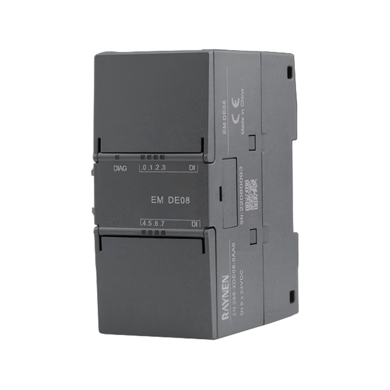
MODEL |
EM DE08 |
EM DE16 |
|
Selected CPU |
RN 288-2DE08-0AB0 |
RN 288-2DE16-0ABO |
|
CONVENTIONAL |
||
|
Dimensions(WxHxD)(mm) |
45×100×81 |
|
|
Power Consumption |
1.5 W |
2.3W |
|
Current Consumption(SM Bus) |
105 mA |
|
|
Current Consumption(24V DC) |
4 mA per input point |
|
|
Cable Length |
500m(shielded), 300m (unshielded) |
|
|
NUMBER INPUT |
||
|
Input Points |
8 |
16 |
|
Type |
Drain/Source |
|
|
Rated Voltage |
24 V DC at 4 mA, rated |
|
|
Permissible Continuous Voltage |
Maximum 30V DC |
|
|
Surge Voltage |
35 V DC, for 0.5 s |
|
|
Logic 1 Signal(Minimum) |
15 V DC at 2.5 mA |
|
|
Logic O Signal(Maximum) |
5V DC at 1 mA |
|
|
Isolation(Field Side to Logic Side) |
500 V DC, for 1 min |
|
|
MODEL |
EM DR08 |
EM DT08 |
EM QR16 |
EM QT16 |
|
Selected CPU |
RN 288-2DR08-0ABO |
RN 288-2DT08-0AB0 |
RN 288-2QR16-0AB0 |
RN 288-2QT16-0AB0 |
|
CONVENTIONAL |
||||
|
Dimensions WxHxD(mm) |
45×100×81 |
|||
|
Power Consumption |
4.5 W |
1.5 W |
4.5W |
1.7W |
|
Current Consumption(SM Bus) |
120 mA |
120 mA |
110 mA |
120 mA |
|
Cable Length |
500 m(shielded), 150m(unshielded) |
|||
|
DIGITAL OUTPUT |
||||
|
Number of Output Points |
8 |
16 |
||
|
Type |
Relay, single contact |
transistor |
Relay, Contacts |
Transistor |
|
Voltage Range |
5~30V DC or5~250V AC |
20.4~28.8 V DC |
5~30V DC or5~250V AC |
20.4~28.8V DC |
|
Logic 1 Signal at Maximum Current |
- |
20V |
- |
20V |
|
Logic O Signal with 10 KΩ Load |
- |
0.1 V |
- |
0.1 V |
|
Rated Current per Point(Maximum) |
2.0 A |
0.75 A |
2.0A |
0.75 A |
|
Lamp Load |
30W DC/200W AC |
5 W |
30W DC/200W AC |
5W |
|
On-State Contact Resistance |
Maximum 0.2Ω for new devices |
0.6Ω |
New equipment maximum 0.2Ω |
0.6Ω |
|
Leakage Current per Point |
- |
10 μA |
- |
10 μA |
|
Surge Current |
7 A when contacts are closed |
8 A, lasting 100 ms |
Contact closed:7 A |
8 A, for 100 ms |
|
Isolation(Field Side to Logic Side) Isolation Resistance Insulation Between Disconnect Contacts |
1500 V AC for 1 min Minimum 100 MQ for new devices 750VAC for 1 min |
500 V AC, sustain 1 min - - |
1500 VAC, 1 min New equipment maximum 100 MΩ 750 VAC, 1 min |
500 VAC, for 1 min - - |
|
Current at Each Common Terminal(Maximum) |
8A |
3A |
8A |
3A |
|
Switching Delay |
Maximum 10 ms |
The longest time from disconnect to connection is 50 μs. The longest time from connection to disconnect is 200 μs. |
Maximum 10 ms |
Maximum on-off time:50 μs Maximum on-off time:200 μs |
|
Mechanical Life(No Load) |
10 million open/close cycles |
- |
10 million open/close cycles |
- |
|
Contact Life under Rated Load |
100, 000 open/close cycles |
- |
100, 000 open/close cycles |
- |
|
Output Status in STOP Mode |
Previous or replacement value (default is O) |
|||
|
MODEL |
EM DR16 |
EM DT16 |
EM DR32 |
EM DT32 |
|
Selected CPU |
RN 288-2DR16-0ABO |
RN 288-2DT16-0AB0 |
RN 288-2DR32-0ABO |
RN 288-2DT32-0AB0 |
|
CONVENTIONAL |
||||
|
Dimensions WxH×D(mm) |
45×100×81 mm |
70×100×81 |
||
|
Power Consumption |
5.5 W |
2.5 W |
10 W |
4.5 W |
|
Current Consumption(SM Bus) |
145 mA |
145 mA |
180 mA |
185 mA |
|
Input Current Consumption |
4 mA per point input |
|||
|
Output Current Consumption |
11 mA per relay coil |
- |
Each relay coil used is 11 mA. |
- |
|
Cable Length |
500 m(shielded), 150 m(unshielded) |
|||
|
NUMBER INPUT |
||||
|
Number of Input Points |
8 |
8 |
16 |
16 |
|
Type |
Drain/Source |
|||
|
Rated Voltage |
24V DC at 4 mA, rated |
|||
|
Permissible Continuous Voltage |
30 V DC max |
|||
|
Surge Voltage |
35V DC, 0.5 s |
|||
|
Logic 1 Signal (Minimum) |
15 V DC |
|||
|
Logic O Signal(Maximum) |
5V DC |
|||
|
Isolation (Field Side to Logic Side) |
500 V AC, 1 min |
|||
|
DIGITAL OUTPUT |
||||
|
Output Points |
8 |
8 |
16 |
16 |
|
Type |
Relay, dry contact |
Transistor |
Relay, dry contact |
Transistor |
|
Voltage Range |
5~30V DC or 5~250V AC |
20.4~28.8 V DC |
5~30V DC or 5~250V AC |
20.4~28.8 V DC |
|
Logic 1 Signal at Maximum Current |
- |
Minimum 20V DC |
- |
Minimum 20V DC |
|
Logic O Signal for 10 KΩ Load |
Maximum 0.1V DC |
- |
Maximum 0.1V DC |
|
|
Rated Current per Point(Maximum) |
2 A |
0.75 A |
2A |
0.75 A |
|
Lamp Load |
30W DC/200W AC |
5W |
30W DC/200W AC |
5W |
|
On-State Contact Resistance |
The new equipment has a maximum Q of 0.2Ω. |
Maximum 0.6Ω |
New equipment maximum 0.2Ω |
Maximum 0.6Ω |
|
Leakage Current per Point |
- |
Maximum 10 μA |
- |
Maximum 10μA |
|
Inrush Current |
When the contacts are closed, 7 A |
8 A, maximum duration 100 ms |
Contact closed 7 A |
8 A, maximum duration 100 ms |
|
Isolation(Field Side to Logic Side) |
1500 V AC, for 1 min. |
500 V AC, duration 1 min |
1500 VAC, lasting 1 min |
500 V AC, duration 1 min |
|
Isolation Resistance |
New device minimum 100 MΩ |
- |
New equipment minimum 100 MΩ |
- |
|
Insulation Disconnection Between Contacts |
750V AC, for 1 min |
- |
750 VAC, for1 min |
- |
|
Current at Each Common Terminal |
8 A |
3A |
8A |
6 A |
|
Inductor Clamping Voltage |
- |
-48V |
- |
-48 V |
|
Switching Delay |
Maximum 10 ms |
Maximum disconnect to connection time:50μs Maximum connection to disconnect time:200 μs |
Maximum 10 ms |
Maximum disconnect to connection time:50 μs Maximum connection to disconnect time:200 μs |
|
Mechanical Life(No Load) |
10 million open/close cycles |
10 million open/close cycles |
- |
|
|
Contact Life under Rated Load |
100, 000 open/close cycles |
- |
100, 000 open/close cycles |
- |
|
Output Status in STOP Mode |
Previous or replacement value (default is O) |
- |
||
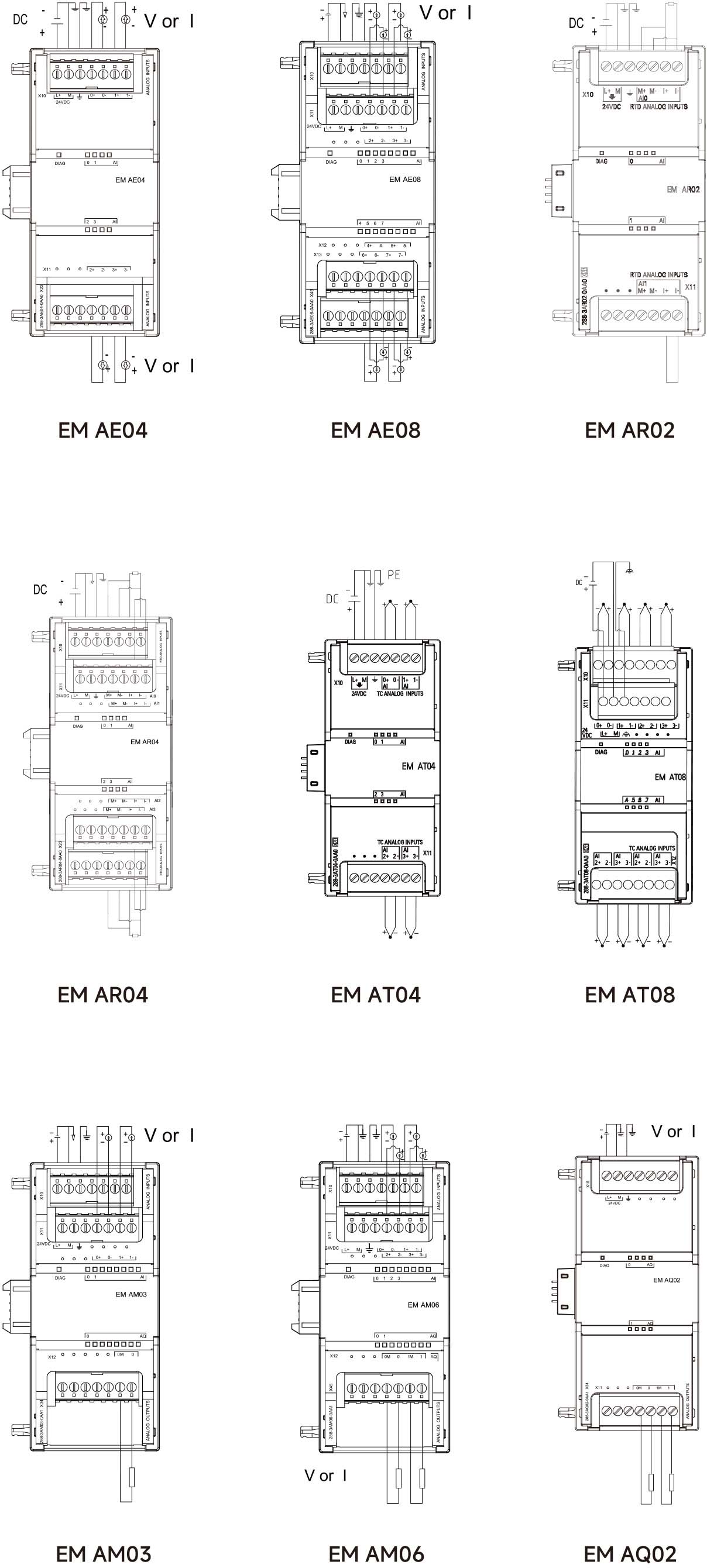
EXTENDED MODULE
ANALOG INPUT MODULE TECHNICAL SPECIFICATIONS
|
MODEL |
EM AE04 |
EM AE08 |
|
Selected CPU |
RN 288-3AE04-0ABO |
RN 288-3AE08-0AB0 |
|
CONVENTIONAL |
||
|
Dimensions WxHxD(mm) |
45x 100x 81 |
|
|
Power Consumption |
1.5 W(no load) |
2.0 W(no load) |
|
Current Consumption(SM Bus) |
80 mA |
|
|
Current Consumption(24 V DC) |
40 mA(no load) |
70 mA(no load) |
|
ANALOG INPUT |
||
|
Number of Input Channels |
4 |
8 |
|
Type |
Voltage or Current(Differential):Selectable in groups of 2 |
|
|
Range |
±10 V, ±5 V, ±2.5 V, or0~20 mA |
|
|
Full Scale Range(Data Word) |
-27, 648~27, 648 |
|
|
Overshoot/Undershoot Range(Data Word) |
Voltage:27, 649~32, 511/-27, 649~-32, 512/Current:27, 649~32, 511/-4864~0 |
|
|
Overflow/Underflow(Data Word) |
Voltage:32, 512~32, 7671-32, 513~-32, 768/Current:32, 512~32, 7671-4, 865~-32, 768 |
|
|
Resolution |
Voltage Mode:12-bit+Sign Bit/Current Mode:12-bit |
|
|
Maximum Voltage/Current Withstand |
±35V/±40 mA |
|
|
Smoothing |
None, Weak, Medium, or Strong |
|
|
Noise Suppression |
400, 60, 50, or 10 Hz |
|
|
Isolation (Field Side vs.Logic Side) |
None |
|
|
Accuracy(25℃10~55℃) |
Voltage mode:±0.1%/±0.2%of full scale /Current mode:±0.2%/±0.3%of full scale |
|
|
Common Mode Rejection |
40 dB, DC to 60 Hz |
|
|
Operating signal range |
The common-mode voltage applied to the signal must be less than+12V and greater than-12 V. |
|
|
Cable length(maximum) |
100 m, shielded twisted-pair cable. |
|
|
DIAGNOSIS |
||
|
Overflow/Underflow |
√ |
|
|
24V DC Low Voltage |
√ |
|
|
MODEL |
EM AQ02 |
EM AQ04 |
|
Selected CPU |
RN 288-3AQ02-0ABO |
RN 288-3AQ04-0ABO |
|
CONVENTIONAL |
||
|
Dimensions WxHxD(mm) |
45x 100x81 |
|
|
Power Consumption |
1.5 W(no load) |
2.1 W(no load) |
|
Current Consumption(SM Bus) |
60 mA |
|
|
Current Consumption(24V DC) |
50 mA(no load) |
75 mA(no load) |
|
ANALOG OUTPUT |
||
|
Number of Output Channels |
2 |
4 |
|
Type |
Voltage or Current |
|
|
Range |
±10V or 0~20 mA |
|
|
Resolution |
Voltage Mode:11-bit +Sign Bit /Current Mode:11-bit |
|
|
Full Scale Range(Data Words) |
Voltage:-27, 648~27, 648 |
|
|
Accuracy(25℃/0~55℃) |
±0.5%/±1.0%of Full Scale |
|
|
Output Status in STOP Mode |
Previous or Replacement Value(Default is O) |
|
|
Isolation (Field Side and Logic Side) |
None |
|
|
Cable Length(Maximum) |
100 m, Shielded Twisted Pair Cable |
|
|
DIAGNOSIS |
||
|
Overflow/underflow |
√ |
|
|
Short circuit to ground (voltage mode only) |
None available |
|
|
Open circuit (current mode only) |
None available |
|
|
24 V DC low voltage |
√ |
|
EXTENDED MODULE
ANALOG INPUT/OUTPUT MODULE TECHNICAL SPECIFICATIONS
|
MODEL |
EM AM03 |
EM AM06 |
|
Selected CPU |
RN 288-3AM03-0ABO |
RN 288-3AM06-0AB0 |
|
CONVENTIONAL |
||
|
Dimensions WxHxD(mm) |
45×100x81 |
|
|
Power Consumption |
1.1 W(No load) |
2.0 W(No load) |
|
Current Consumption(SM Bus) |
60 mA |
80 mA |
|
Current Consumption(24V DC) |
30 mA(No load) |
60 mA(No load) |
|
Cable Length(Max) |
100m, shielded twisted pair |
|
|
ANALOG INPUT |
||
|
Number of Input Channels |
2 |
4 |
|
Type |
Voltage or Current(Differential):2 can be selected as a group |
|
|
Range |
±10 V, ±5V, ±2.5 V, or 0~20 mA |
|
|
Full Scale Range(Data Word) |
-27, 648~27, 648 |
|
|
Overshoot/Undershoot Range (Data |
Word)Voltage:27, 649~32, 511/-27, 649~-32, 512/Curent:27, 649~32, 5111-4, 864~0 |
|
|
Overflow/Underflow(Data Word) |
Voltage:32, 512~32, 7671-32, 513~-32, 768/Current:32, 512~32, 7671-4, 865~-32, 768 |
|
|
Resolution |
Voltage Mode:12-bit+Sign Bit /Current Mode:12-bit |
|
|
Maximum Voltage/Current Withstand |
±35V/±40 mA |
|
|
Smoothing |
None, Weak, Medium, or Strong |
|
|
Noise Suppression |
400, 60, 50, or 10 Hz |
|
|
Isolation(Field Side vs.Logic Side) |
None |
|
|
Accuracy(25℃/0~55℃) |
Voltage mode:±0.1%/±0.2%of full scale /Current mode:±0.2%/±0.3%of fullscale |
|
|
Common Mode Rejection |
40 dB, DC to 60 Hz |
|
|
Operating Signal Range |
Signal applied common-mode voltage must be less than+12V and greater than -12V |
|
|
ANALOG OUTPUT |
||
|
Number of Output Channels |
1 |
2 |
|
Type |
Voltage or Current |
|
|
Range |
±10 V or 0~20 mA |
|
|
Resolution |
Voltage Mode:11-bit+Sign Bit /Current Mode:11-bit |
|
|
Full Scale Range(Data Words) |
Voltage:-27, 648~27, 648/Current:0~27, 648 |
|
|
Accuracy(25℃/0~55℃) |
Full Scale±0.5%/±1.0% |
|
|
Output Status in STOP Mode |
Previous Value or Replacement Value(Default Value is O) |
|
|
Isolation(Field Side and Logic Side) |
None |
|
|
DIAGNOSIS |
||
|
Overflow/Underflow |
√ |
|
|
Short circuit to ground(voltage mode only) |
None available |
|
|
Open circuit(current mode only) |
None available |
|
|
24V DC Low Voltage |
√ |
|
EXTENDED MODULE
THERMOCOUPLE MODULE TECHNICAL SPECIFICATIONS
|
MODEL |
EM AT04 |
EM AT08 |
||||||||
|
Selected CPU |
RN 288-3AT04-0ABO |
RN 288-3AT08-0ABO |
||||||||
|
CONVENTIONAL |
||||||||||
|
Dimensions WxH×D(mm) |
45×100×81 |
|||||||||
|
Power Consumption |
1.5 W |
|||||||||
|
Current Consumption(SM Bus) |
80 mA |
|||||||||
|
Current Consumption(24 V DC) |
40 mA |
|||||||||
|
ANALOG INPUT |
||||||||||
|
Number of Input Channels |
4 |
8 |
||||||||
|
Resolution /Temperature Resistance |
0.1℃/0.1F/15 bits+sign |
|||||||||
|
Maximum Withstand Voltage |
±35V |
|||||||||
|
Noise Suppression |
85 dB for selected filter settings(10 Hz, 50 Hz, 60 Hz, or 400 Hz) |
|||||||||
|
Common Mode Rejection |
>120 dB at 120 V AC |
|||||||||
|
Impedance |
≥10 MΩ |
|||||||||
|
Isolation /Field Side to Logic Side Field Side to 24V DC Side 24V DC Side to Logic Side |
500 V AC 500 V AC 500 V AC |
|||||||||
|
Channel Isolation |
- | |||||||||
|
Accuracy |
Refer to thermocouple selection table |
|||||||||
|
Repeatability |
±0.05% FS |
|||||||||
|
Measurement Principle |
Integrating type |
|||||||||
|
Module Update Time |
Refer to filter selection table |
|||||||||
|
Cold Junction Temperature Error |
±1.5℃ |
|||||||||
|
Cable Length(Maximum) |
Maximum length to sensor is 100 meters |
|||||||||
|
Cable Resistance |
Maximum 100Ω |
|||||||||
|
DIAGNOSIS |
||||||||||
|
Overflow/Underflow |
√ |
|||||||||
|
Open Circuit |
√ |
|||||||||
|
24V DC Low Voltage |
√ |
|||||||||
|
ATO8-DIP SWITCH CORRESPONDENCE TABLE(↑ ON=1, ↓OFF =0) |
||||||||||
|
SW1 |
SW2 |
SW3 |
SW4 |
SW5 |
SW6 |
SW7 |
SW8 |
|||
|
Thermocouple type |
spare |
Short-line detection direction |
Disconnection detection switch |
Temperature display |
Cold section compen sation switch |
|||||
|
K |
0 |
0 |
0 |
-- |
0 indicates a broken line(positive) |
0 Enabled |
0 degrees Celsius |
0 Enable |
||
|
J |
0 |
0 |
1 |
-- |
1 Disabled |
1 degree Fahrenheit |
1 Disable |
|||
|
T |
0 |
1 |
0 |
-- | ||||||
|
N |
0 |
1 |
1 |
-- |
1 indicates a broken line (negative) |
|||||
|
E |
1 |
0 |
0 |
-- | ||||||
|
R |
1 |
0 |
1 |
-- |
||||||
|
S |
1 |
1 |
0 |
-- |
||||||
|
±80 mV |
1 |
1 |
1 |
-- |
||||||
EXTENDED MODULE
TECHNICAL SPECIFICATIONS FOR RESISTANCE TEMPERATURE MODULES
|
MODEL |
EM AR02 |
EM AR04 |
|
Selected CPU |
RN 288-3AR02-0AB0 |
RN 288-3AR04-0ABO |
|
CONVENTIONAL |
||
|
Dimensions W×HxD(mm) |
45×100x 81 |
|
|
Power Consumption |
1.5 W |
|
|
Current Consumption(SM Bus) |
80 mA |
|
|
Current Consumption(24V DC) |
40 mA |
|
|
ANALOG INPUT |
||
|
Number of Input Channels |
2 |
4 |
|
Type |
Module Reference Ground RTD and Resistance Value |
|
|
Resolution /Temperature Resistance |
0.1℃/0.1°F/15 bits +sign bit |
|
|
Maximum Withstand Voltage |
±35 V |
|
|
Noise Suppression |
85 dB, 10 Hz/50 Hz/60 Hz/400 Hz |
|
|
Common Mode Rejection |
>120 dB |
|
|
Impedance |
≥10 MΩ |
|
|
Isolation |
500 V AC |
|
|
Channel Isolation |
- |
|
|
Accuracy |
Please refer to the RTD sensor selection table |
|
|
Repeatability |
±0.05%FS |
|
|
Maximum Sensor Power Consumption |
0.5m W |
|
|
Measurement Principle |
Integral |
|
|
Module Update Time |
Please refer to the noise reduction selection table |
|
|
Cable Length (Maximum) |
Maximum length to sensor:100 m |
|
|
Cable Resistance |
Maximum 20 Ω, maximum 2.7 Ω for Cu10 |
|
|
DIAGNOSIS |
||
|
Overflow/Underflow |
√ |
|
|
Open Circuit |
√ |
|
|
24 V DC Low Voltage |
√ |
|
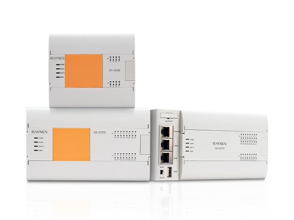
INNOVATIVE DISTRIBUTED I/O, FLEXIBLE EFFICIENT
PROFINET SLAVE MODULE IM155
Features
The Profinet IM155 slave module comes with two RJ45 network ports and supports expansion with eight RN 200 SMART series I/O modules, including digital, analog, and temperature modules. It can be easily expanded and networked to build a distributed I/O system, providing greater flexibility and scalability.
The IM155 is fully compatible with Siemens TIA portal and SMART programming software. No additional learning is required, allowing for quick and easy setup, saving time and resources.
The IM155 widely supports multiple third-party PN master stations, including S7-1200, S7-1500, S7-300, and S7-200 SMART.

|
MODEL |
|||
|
Selected CPU |
RN 155-1PN01-0ABO |
||
|
POWER CHARACTERISTICS |
|||
|
Rated voltage |
DC 24V |
Inrush current |
12A, 28.8V DC |
|
Input voltage |
DC 20.4-28.8V |
Fuse current |
2A 60V slow melt |
|
Input current |
100mA(at DC 24V) |
Bus current |
Maximum 0.8A |
|
LED INDICATOR DEFINITION |
|||
|
DIAG(Red)/(Green) |
ON:Red:Bus error, configuration error, module error, communication disconnected from PLC OFF:24V power not connected Green:No error |
L(green) |
ON:Solid:Profinet bus communication is normal Blinking:Profinet bus communication failure, disconnected from the PLC OFF:No "valid connection"on either RJ45-1 or RJ45-2 network (Connected to PLC or switch) |
|
PIR/P2R(RJ45 green indicator light) |
ON:Connection to switch/PN master station present /OFF:Connection to switch/PN master station absent |
||
|
PIR/P2R(RJ45 green indicator light) |
ON:Data transmission/reception to switch/PN master station present /OFF:Data transmission/reception to switch/PN master station absent |
||
|
PHYSICAL PROPERTIES |
|||
|
Size(W*H*D) |
45×100×81mm |
Power consumption 2.5 W(Body) |
|
|
DEVELOPMENT I/O CAPABILITY |
|||
|
Native I/O |
No |
Topology |
Supports star, tree, and linear topologies. |
|
Protocol Type |
SMART backplane bus protocol |
||
|
Maximum Supported Modules |
Up to 8(any combination)SMART series modules Standard digital, analog, and temperature modules |
Maximum I/O Configuration |
Maximum analog input configuration:64AI/64AQ Maximum digital input configuration:256DI/256DQ |
|
PROFINET COMMUNICATIONS |
|||
|
Communication interface |
2 RJ45 Ethernet ports |
||
|
Data transmission rate |
thernet transmission rate:10/100Mbps /Profinet transmission rate:10/100Mbps, full-duplex |
||
|
Supported Ethernet services |
Ping, ARP, Network Diagnosis(SNMP)/MIB-2, LLDP |
||
|
Send cycle |
250μs~4ms |
||
|
HARDWARE CONFIGURATION FUNCTION |
|||
|
Import File Type |
PROFINET slave device GSD description file in .XML format |
||
|
Third-Party PN Main Site |
CPUs supporting Profinet master interface, such as S7-1200, S7-1500, S7-300, and S7-SMART. |
||
SCALABLE SIGNAL VERSION
DIGITAL INPUT/OUTPUT SIGNAL BOARD TECHNICAL SPECIFICATIONS
Only supports RN 200 SMART (not compatible with S7 series PLCs)
|
MODEL |
SB DT04 |
||
|
Selected CPU |
RN 288-5DT04-0AB0 |
||
|
CONVENTIONAL |
|||
|
Dimensions WxHxD(mm) |
35×52.2×16 |
Current consumption(SM bus) 50 mA |
|
|
Power Consumption |
1.0 W |
Current consumption(24V DC)4 mA per input point |
|
|
DIGITAL INPUT |
|||
|
Number of Input Points |
2 |
Logic 0 signal (maximum) |
5V DC at 1 mA |
|
Type |
Drain type(IEC Class 1 drain type) |
Isolation (field side to logic side) |
500 V AC for 1 min |
|
Rated Voltage |
24V DC at 4 mA, rated |
lsolation group |
1 |
|
Permissible Continuous Voltage |
30 V DC max |
Number of inputs simultaneously enabled |
2 |
|
Surge Voltage |
35 V DC, duration 0.5 s |
Cable length |
500 m(shielded), 300 m(unshielded) |
|
Logic 1 Signal(Minimum) |
15V DC at 2.5 mA |
||
|
Filtering Time |
Individually selectable durations per channel:0.2, 0.4, 0.8, 1.6, 3.2, 6.4, and 12.8μs |
||
|
DIGITAL OUTPUT |
|||
|
Number of Output Points |
2 |
Overload Protection |
None |
|
Output Type |
Transistor |
Isolation(Field Side vs.Logic Side) |
500 V AC, continuous for 1 min |
|
Voltage Range |
20.4~28.8V DC |
Isolation Group |
1 |
|
Logic 1 Signal at Maximum Current |
Minimum 20V DC |
Current at Each Common Terminal |
1A |
|
Logic O Signal at Maximum Current |
Maximum 0.1 V DC |
Inductor Clamping Voltage |
L+-48 V, 1 W loss |
|
Rated Current per Point(Maximum) |
0.5 A |
Switch Delay |
Maximum disconnect to on time:2 μs |
|
Lamp Load |
5W |
Maximum on to disconnect time:10 μs |
|
|
On-State Contact Resistance |
Maximum 0.6Ω |
Output Status in STOP Mode |
Previous or replacement value(default is O) |
|
Leakage Current per Point |
Maximum 10μA |
Number of Simultaneously Connected Outputs |
2 |
|
Inrush Current |
5 A, maximum duration 100 ms |
Cable Length(Maximum) |
500 m(shielded), 150 m(unshielded) |
|
O ANALOG INPUT SIGNAL BOARD TECHNICAL SPECIFICATIONS Only supports RN 200 SMART(not compatible with S7 series PLCs) |
|||
|
MODEL |
SB AE01 |
||
|
Order number |
RN 288-5AE01-0AB0 |
||
|
CONVENTIONAL |
|||
|
Dimensions WxHxD(mm) |
35×52.2×16 |
Power consumption |
0.4 W |
|
Current consumption(5V DC) |
50 mA(5V and 3.3V combination) |
||
|
ANALOG INPUT |
|||
|
Input Points |
1 |
Full-scale range(data words) |
-27, 648~27, 648 |
|
Type |
Voltage or current(differential) |
Cable length(maximum value) |
100m, shielded twisted pair |
|
Range |
±10 V, ±5 V, ±2.5V or 0~20 mA |
Resolution |
Voltage:11 bits +sign bit Current:11 bits |
|
DIAGNOSIS |
|||
|
Overflow/Underflow |
√ |
||
SCALABLE SIGNAL VERSION
ANALOG OUTPUT SIGNAL BOARD TECHNICAL SPECIFICATIONS
Only supports RN 200 SMART (not compatible with S7 series PLCs)
|
MODEL |
SB AQ01 |
||
|
Selected CPU |
RN 288-5AQ01-0ABO |
||
|
CONVENTIONAL |
|||
|
Dimensions WxH×D(mm) |
35×52.2×16 |
Current consumption(SM bus) |
15 mA |
|
Power Consumption |
1.5 W |
Current consumption(24V DC) |
40 mA(no load) |
|
ANALOG OUTPUT |
|||
|
Output Points |
1 |
Load impedance |
Voltage:≥1000 Ω Current:≤600 Ω |
|
Type |
Voltage or Current |
Output status in STOP mode |
Previous or Replacement Value |
|
Range |
±10 V, 0~20 mA |
Isolation(Field side vs.Logic side) |
None |
|
Resolution |
Voltage:11 bits+sign bit Current:11 bits |
Cable length (maximum) |
10m, Shielded Twisted Pair Cable |
|
Full Scale Range(Data Words) |
-27, 648~27, 648(-10V~10V)/0~27, 648( |
0~20 mA) |
|
|
DIAGNOSIS |
|||
|
Overflow/Underflow |
√ |
||
|
O RS485 SIGNAL BOARD TECHNICAL SPECIFICATIONS Only supports RN 200 SMART(not compatible with S7 series PLCs) |
|||
|
MODEL |
SB CM01 |
||
|
Order number |
RN 288-5CM01-0AB0 |
||
|
CONVENTIONAL |
|||
|
Dimensions WxHxD(mm) |
35×52.2×16 |
Current consumption(SM bus) 50 mA |
|
|
Power Consumption |
0.5 W |
Current consumption(24 V DC)not applicable |
|
|
TRANSMITTER AND RECEIVER(RS485) |
|||
|
Common mode voltage range |
-7 V~+12 V, 1 s, 3 VRMS continuous |
||
|
Cable length |
With isolation repeater:1000 m, baud rate up to 187.5 kHz |
||
|
Shielded cable |
Without isolation repeater:50 m |
||
|
O BATTERY SIGNAL BOARD TECHNICAL SPECIFICATIONS Only supports RN 200 SMART(not compatible with S7 series PLCs) |
|||
|
MODEL |
SB BA01 |
||
|
Order number |
RN 288-5BA01-0AB0 |
||
|
CONVENTIONAL |
|||
|
Dimensions W×H×D(mm) |
35×52.2×16 |
Power consumption |
0.6 W |
|
BATTERIES(TO BE PURCHASED SEPARATELY) |
|||
|
Retention time |
Approximately 1 year |
Rated voltage |
3 V |
|
Battery type |
CR1025 button battery |
Rated capacity |
30 mAH |
|
DIAGNOSIS |
|||
|
Battery Diagnosis |
Low Voltage Indicator: A low battery voltage will cause the LED on the BA01 panel to remain constantly red as a diagnostic alarm. Or, if the battery is low, the digital input I7.0=1. |
||
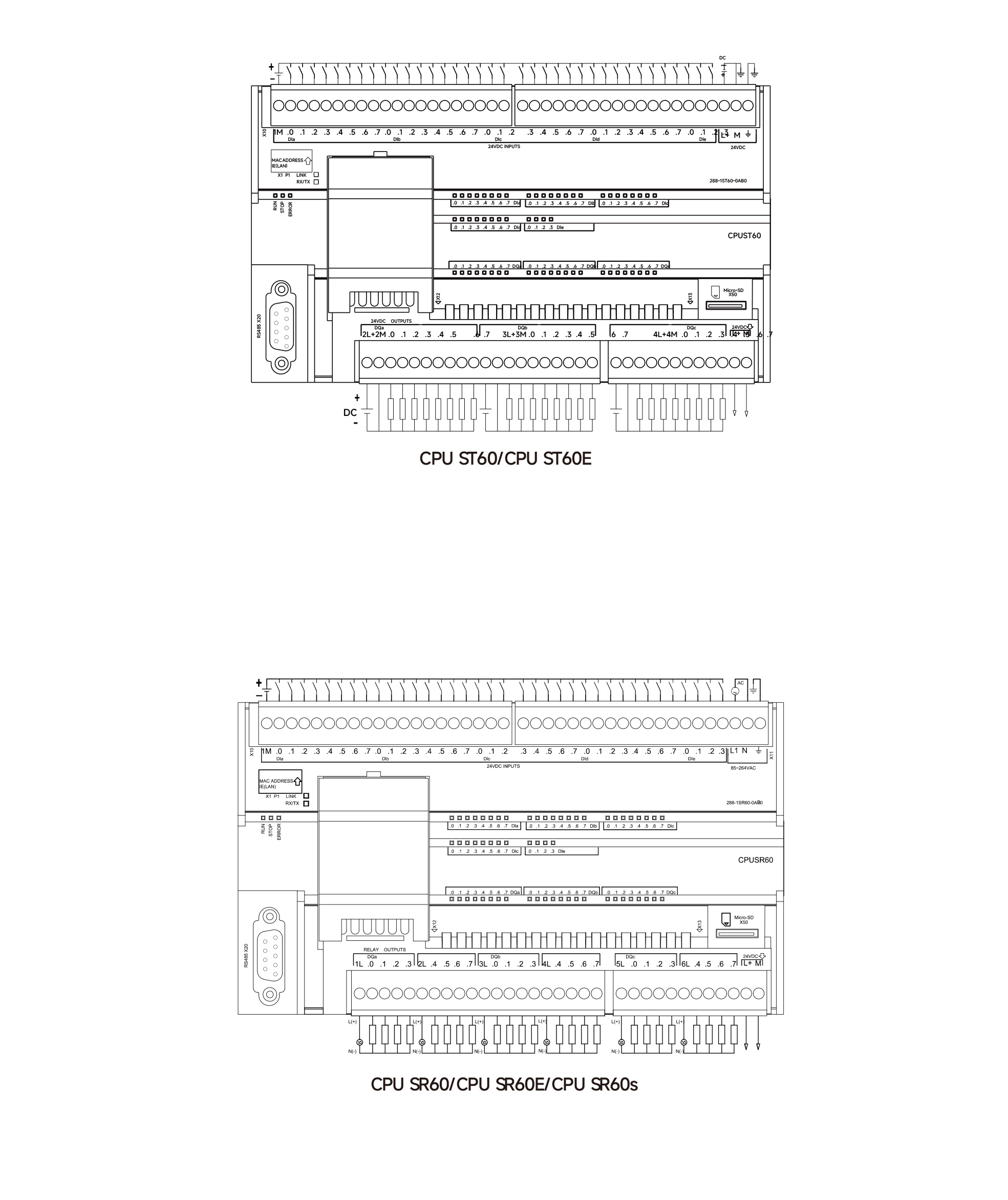
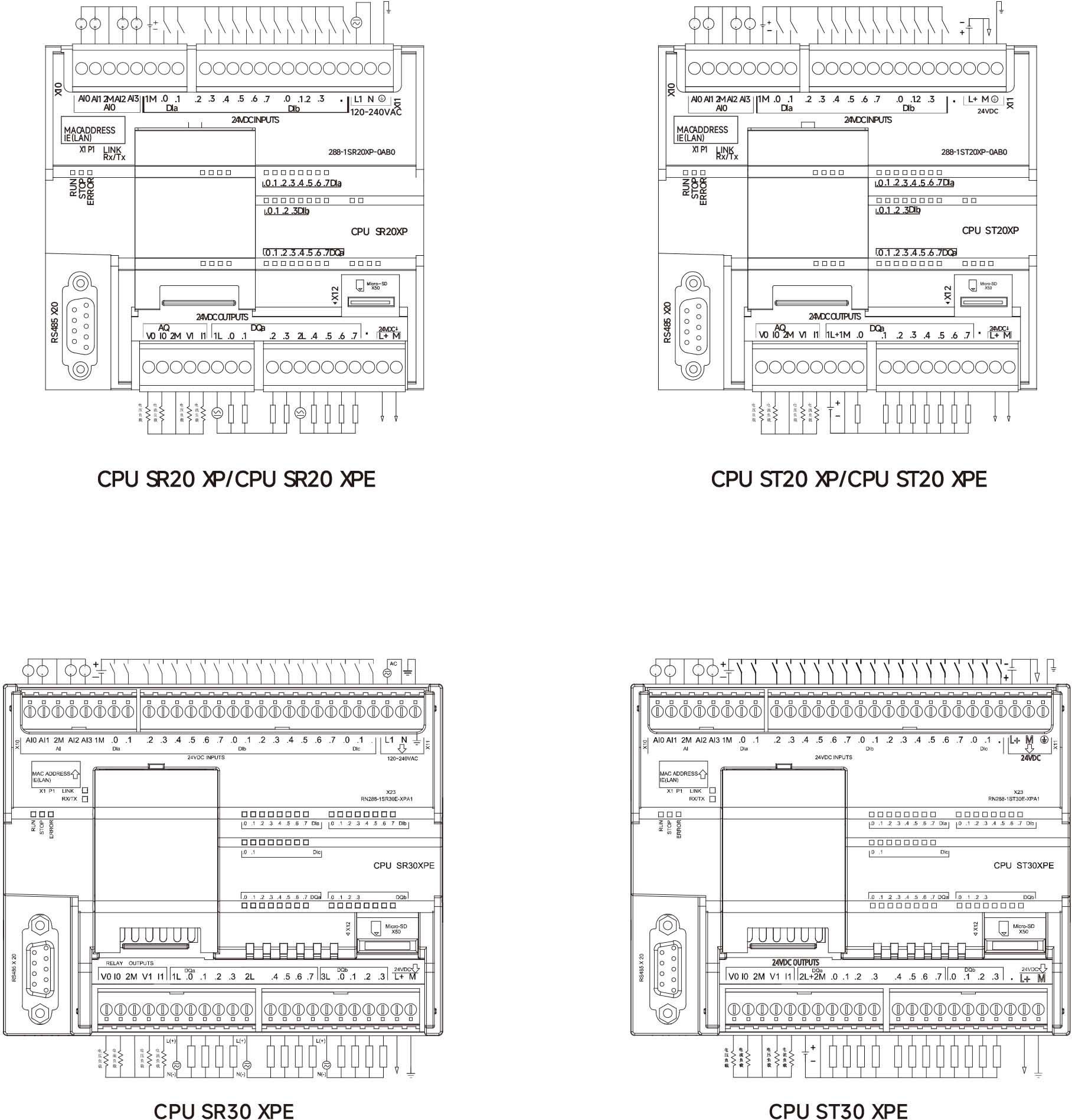
200 SMART CPU WIRING DIAGRAM
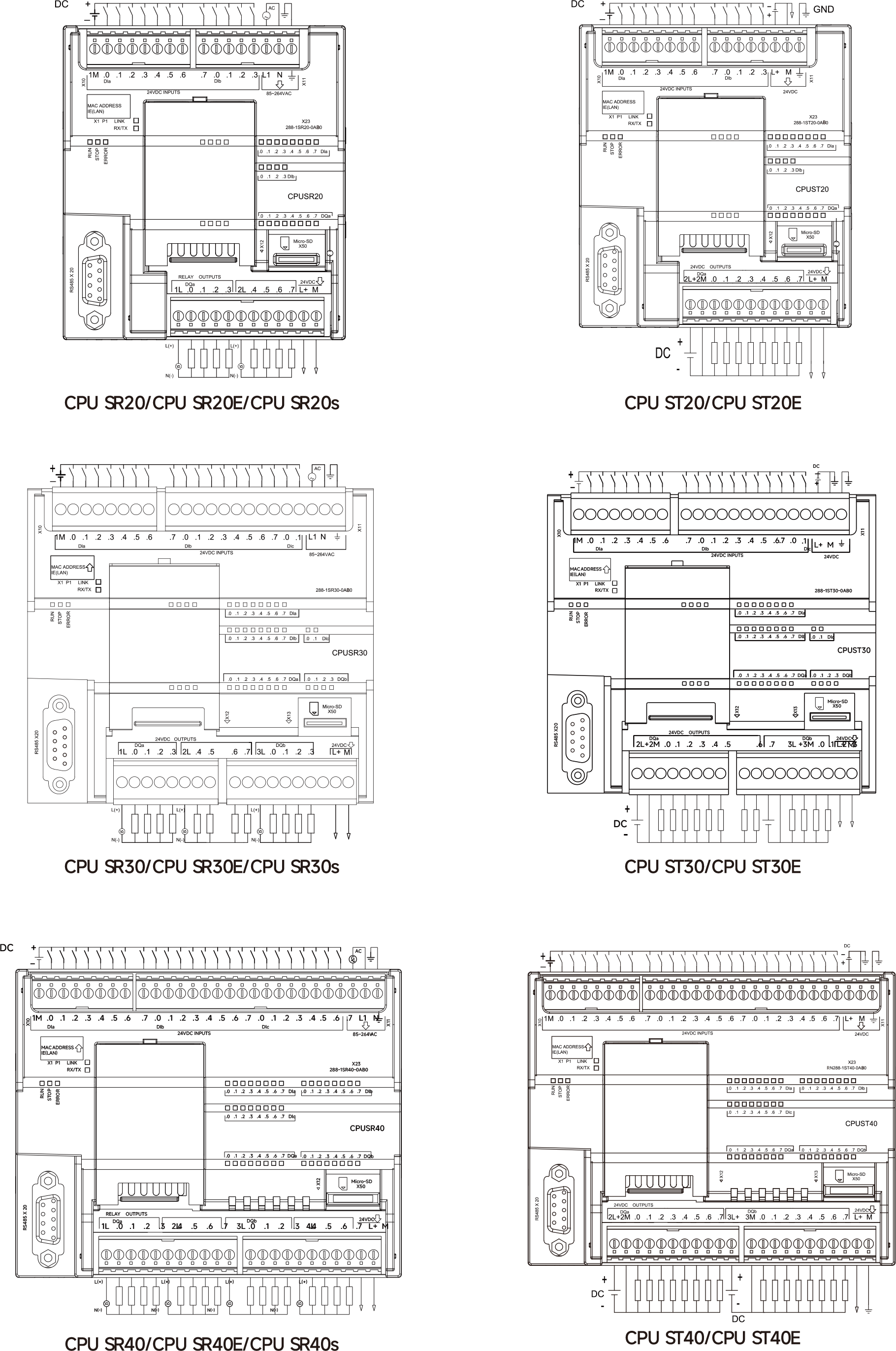
COMMUNICATION PORT PIN DEFINITIONS
|
LEGEND |
SERIAL |
PORT PIN |
PIN DEFINITIONS |
REMARK |
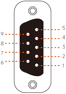 |
PORTO |
1 |
/ |
PORT0 supports PPI, free port, and Modbus-RTU. |
|
2 |
GND |
|||
|
3 |
A+ |
|||
|
8 |
B- |
|||
|
5 |
GND |
|||
|
6 |
5V |
|||
|
7 |
24V |
|||
|
PORT2 |
4 |
A+(Selected Support) |
PORT2 only supports Raynn SMART's Mod-bus-RTU library. |
|
|
9 |
B-(Selected Support) |
THE RN 200 SMART EM RTD MODULE CAN ALSO DETECT RESISTANCE SIGNALS. RESISTORS ARE AVAILABLE IN TWO-WIRE, THREE-WIRE, AND FOUR-WIRE CONFIGURATIONS. THE WIRING DIAGRAM FOR THE EM RTD MODULE IS SHOWN BELOW:
-11(15)kW VFD")
-3(4)kW VFD")
kW VFD")